Soil-Pipes And Their Disconnection And Ventilation. Part 3
Description
This section is from the book "Principles And Practice Of Plumbing", by S. Stevens Hellyer. Also available from Amazon: Principles and practice of plumbing.
Soil-Pipes And Their Disconnection And Ventilation. Part 3
(a) In a building of great height, with closets on the upper and lower floors entering a stack, to prevent syphon-age of the closet traps the pipe should be of larger size than in the case of a. two, three, or four-storied house. (See Chap. XXIII., Art. 3.)
(6) The size should also depend upon the treatment it is likely to receive. In a private house a 2 1/2 in. pipe would be less liable to chokage than a 3 1/2 in. in an hotel. All sorts of things are thrown into hotel closets, and if there is to be no blockage of the soil-pipe it is obvious that whatever can be passed through a closet, where it is often assisted by the prodding of some instrument, must be able to pass still more freely through the soil-pipe.
(c) Where valve-closets are fixed, and the face-plates of their basin-valves are of earthenware, the pipe should be large enough for the broken parts to pass through it, or the face-plates should be made of unbreakable material.
14. Branches into minor branches, or into main pipes, should always be made to enter a pipe in the direction of the current by Y-shaped connections, as shown in figs. 112 and 112a, and never at right angles, or T-shaped, as shown in fig. 47, Chap. XVII.
A diagrammatic section of a range of closet traps is given in fig. 113, to show the errors of bad branching and bad ventilation. An excrementitious discharge through any of the traps, c, d, e, would wash up into the branch pipe, and foul it; and any matters in this way back-washed up into the branch would remain there until a closet higher up was used; but anything which got washed back beyond the furthest closet, e, would remain in the pipe, to send off bad air through the badly arranged ventilation-pipe, F, even if in time this pipe did not get completely blocked up in the bend, or between the bend and the branch, b1.
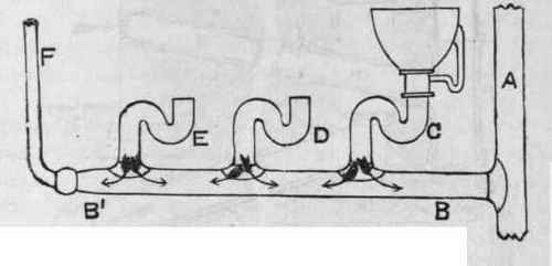
Fig. 113. - Showing bad Branching.
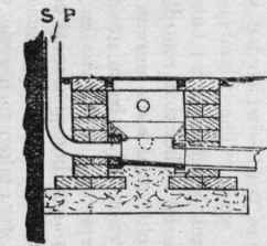
15. Where a stack of soil-pipe would be in communication with a foul drain, or an old brick drain which the householder or owner will not remove, instead of allowing the air from such a drain to pass into the soil-pipe, it should be excluded by a disconnecting trap, as shown at s (fig. 112), or as shown in fig. 114, or in some such way. Fresh air can be taken into the foot of the soil-pipe from any convenient point. When it stands close to the soil-pipe, where any air driven out of it - by a discharge sent through the soil-pipe - would enter the house through an adjacent door or window, the mouth of the pipe should be provided with a mica-valve to prevent egress of soil-pipe air.
16. Where a proper system of drainage exists, or is to be laid down, the soil-pipe can be branched directly into the drain, or fixed in continuation of it, as shown in fig.

Fig. 114. - Soil-Pipe Trap, with Foot-Ventilation.
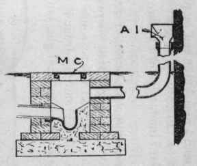
115; and, where it can be afforded, a man-hole should be built, something like that shown in the illustration, and fresh air brought into it from some near point, where no offence would be given to anybody should there be a reaction in the air-current for a minute or two. In some cases it may be desirable to fix a mica-valve over the mouth of the pipe. In some cases a grating can be fixed directly over the man-hole; but more often than not a grating would allow all sorts of surface washings or dirt to pass into the man-hole to foul it. Where the mouth of a fresh-air induct-pipe would stand in a flower bed or place where earth would be liable to fall into it, or gravel or other foreign matter, a standard inlet, as shown in fig. 117, could be fixed on the pipe.
Longitudinal Section.
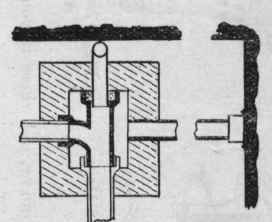
Plan.
Transverse: Section.
Fig. 115.
17. For efficient ventilation it is better to continue the soil-pipe up full bore, or of a larger size where a building is of great height (Chap. XXXIX.), to some point well above the roof, where the air emitted from it would not enter the house through a broken skylight, lantern, trapdoor, chimney, or window, and where it would not contaminate any cistern water.
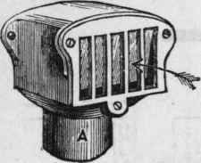
Fig. 116. - View of a Mica-Valve.
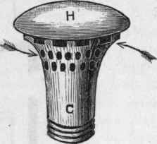
Fig. 117. - "Mushroom" Air-Inlet.
18. The question of cowls - which has been dealt with pretty fully in my work "The Plumber and Sanitary Houses" - is too large to discuss here; but a good kind of cowl, which would assist rather than retard the up-current in a pipe, and which would also prevent or reduce the down-draught, could not fail to be of great advantage in many instances. Especially would this be the case where the mouth of a fresh-air induct-pipe stood near an opening to a house, or near the traffic of foot passengers.
19. Much care is often taken to prevent the passage of soil-pipe air into the room of a closet, but very little care to exclude it from a bedroom (fig. 118). In thousands of instances throughout the United Kingdom the air emitted from the ventilation-pipe of a soil-pipe or drain is as near to a window or opening into a house as the smoke which escapes from the bowl of a churchwarden tobacco-pipe is to the face of the man who smokes it.
20. A lead soil-pipe can be soundly connected to a cast-iron pipe or drain by soldering a brass, gun-metal, or copper ferrule or sheath to the lower part of the pipe, as shown in fig. 119, and running the joint in with molten lead, and caulking it.
As copper is acted upon by faecal matters, as proved by the destruction of copper pans in pan-closets, it is better to carry the lead soil-pipe right down into the socket, where it should be tafted back and soldered to the flanged end of the copper ferrule, to prevent matters back - washing up between the lead pipe and the copper sleeve.
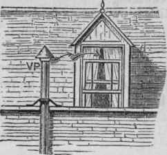
Fig. 118. - Soil-Pipe Terminal. Bad Position.

Fig. 119. - Connection of Lead Soil-Pipe to an Iron Drain.
The copper ferrule must be stout enough to stand the caulking.
21. As shown in the woodcut, fig. 119, a thick flange or base, with a strong web, is cast on the underside of the bend for the purpose of standing it upon a piece of stone laid on a bed of concrete or brickwork, to give a solid support to the vertical pipe. It is known by the name of " duck's-foot " bend.
Continue to:
My Books

