Form Details And Practical Designs. Part 3. Part 2
Description
This section is from the book "Practical Concrete Work for the School and Home", by H. Colin Campbell. Also available from Amazon: Practical concrete work for the school and home.
Form Details And Practical Designs. Part 3. Part 2
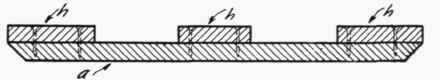
Plates 11, 12 and 13 show various details of a square ornamental flower box such as would be used for a small bay tree or rubber plant. A half section of the form is shown to the left of Plate 12 and makes clear how the separate parts of the form are nailed or screwed together. Part a is made of 7/8 or 1-inch lumber, part d from stock molding, and inner face of c is cut to the slope of the side of the box. Part d is made of half Section through Exterior Form.

Elevation of Bay Tree Box.


Interior Elevation of one Side of Form.
2 pieces of 1-inch stuff, part e of 2-inch stuff. Part f is made from stock molding, g from 1-inch stuff. Parts a, b, and c are held together by cleats h. The two pieces of lumber forming the side are held together by cleats a while the parts e, f and g are held together by cleats /. The outer edge of the depressed panel m is formed by attaching small stock molding n to the pieces d. After all parts are nailed together the mitered joint is cut. This is shown in section and elevation at the lower portion of Plate 13.

Top View of one Side of Form
(Four of these required)
Section on A-A.
By slight extension of use forms similar to those described for flower boxes can be used to build a plain round-topped table with square pedestal, the several parts being cast separately and later assembled. Details of this are shown in Plate 14. The first step is to make the cap form. Pieces a and b shown in the upper right-hand portion of Plate 14 are nailed together and a mitered joint cut. These four pieces thus compose the exterior form for the caps. Cut piece c 5 1/4 inches square with four edges beveled to allow a draft of 1-16 of an inch. This is the core, which is held in exact position by cleat d nailed to it and in turn tacked to the exterior form. The form for the base is made in a similar manner. The form for the shaft of the pedestal is made with square joint except at the sections A-A. Ordinarily no reinforcement is required in the shaft but to prevent possibility of injury from frequent handling it is well to insert small steel rods (1/4 inch) or expanded metal in the concrete.
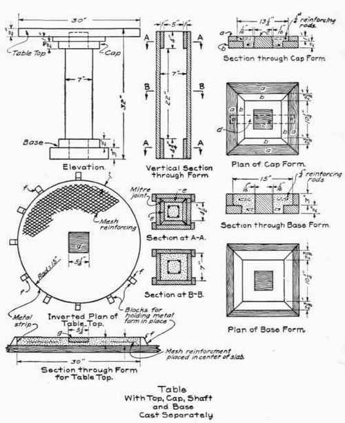
The form for the table top is made by first cutting a piece of thin metal 2 inches wide and 94 1/2 inches long preferably in one piece. This strip is then bent around inside of blocks / which are nailed to the workbench with their inside edges on a line corresponding to the circumference of the table top. The ends of these metal strips should butt together and be nailed to one of the blocks /. Care should be taken not to dent nor otherwise injure the metal strip when setting it up and nailing it in position, otherwise the concrete surface against it will show any irregularities in the metal. Piece g forms the core for a 5 1/4 inch by 5 1/4 inch mortise in the underside of the table top or slab. This core is held in exact position by means of a cleat. Allowance has been made in the sketch for mortise joints where the tenon fits into the mortise. After the concrete has hardened the several parts of the table are assembled and held together by thin mortar previously spread over the parts to be joined.
Reinforcement for the table top may be suitable mesh fabric or expanded metal, preferably with mesh no larger than 1 inch in greatest dimension. It should be placed in the center of the slab and at no place should come nearer than 1 inch to the edge. Before making a table like the one just described and having a cylindrical pedestal instead of a square one a word of caution may be given as to the requirements of form construction for the cylindrical portion. Frequently such forms are cut into two supposedly equal parts. Often, however, the cut is made so that the supposed halves are unequal, that is the cut is made slightly to one side or the other of the true diameter. This makes segment a as shown in Plate 15 larger than segment b. Therefore segment a will cling to the object or cannot be removed without injury to the concrete. This is shown in the center sketch of Plate 15 with the exception that the drawing has been purposely made to exaggerate the curves so that the gripping of the form may be seen. The correct and sure method is to divide the form into three or more parts according to the size of object as shown at the right-hand portion of Plate 15.
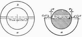
Incorrect method of making Joints for Circular form.

Correct method of maKing Joints for Circular Forms
Plate 16 suggests the best manner of cutting wood so that the grain will run the long way of the pieces regardless of their number. The wood is cut into diagonal sections and fastened together with cleats as shown. The center is then sawed out along the inner dotted circle. Then a saw cut is made along the outer dotted circle. To prevent splitting, pieces of this kind should be of at least 1 1/2 or 2-inch stuff.

Continue to:
My Books

