167. To Make A Pin (249). Part 2
Description
This section is from the book "Bench Work In Wood", by W. F. M. Goss. Also available from Amazon: Bench Work In Wood.
167. To Make A Pin (249). Part 2
Fig. 198
Scale. 3"=1'

Elevation (Face A.) End.

End. Elevation (Face C.).
172. The joint ought to go together by light driving, and be perfectly square on the inside between the working-faces. If it is found to be satisfactory, take it apart, apply a light coating of glue, and drive together again. When the glue is hard, the joint may be smoothed and squared, and the ends of the pieces cut to the dimensions shown in Fig. 199.
173. It will be seen that one part of the joint is made, and the second part is then made to fit the first; hence, the proportions of the first part need not be determined with great exactness. The skilled bench-worker usually proceeds as follows: on the piece X (if there are several pieces, X, he treats them all at the same time) he lays off the lines ab and cross-lines as gh, the latter without measuring, and then saws obliquely without the use of lines as ef; on Y he lays off the lines ad and oblique lines as gh, and saws without making lines as ef. In this way the joint is soon made, and, although not perfectly symmetrical, it may be well-formed and well-fitted.
Fig. 199 Scale, 3"= l'

Plan.

Elevation (B.).

Elevation (A.).
Fig. 200

Exercise No. 12. - Lap, or Drawer, Dovetail.
The stock required is one piece 7/8" x 3 3/4" X 4" and one piece 1/2" X 3 3/4" X 4", edges jointed parallel and one end of each squared. The finished piece is shown by Fig. 201. It will be seen that the piece X does not extend across the full thickness of the piece Y, and, consequently, the end grain does not appear in Elevation B, Fig. 201.
174. On Y, Fig. 202, scribe the line ab, 1/2" (the thickness of X) from the working-end, and continue it across the working-edges. Set a gauge at 5/8", and from the working-face A gauge the line cd on the working-end, and extend it on the edges until it meets the extended line ab, as shown by face D, Fig. 202. From the working-end of X, with the same gauge, make the line ab on the two faces A and C. Produce the remaining lines on X, cut the mortises, and lay off Y by X, as in the last exercise.
Fig. 201 Scale, 8"= l'
Plan.


Elevation (Face B.).

Elevation (Face A.).
Fig. 202 Scale, 3" - 1'

Plan (Face D.).

Elevation (Face A.).

End.
Elevation (Face A.).

End.
In cutting out around the pins (Y), the delicacy of the work does not demand the most delicate chisel, but one as large as is convenient should be used. Finish the joint to the dimensions given by Fig. 201.
Exercise No. 13. - Blind Dovetail.
The stock required is two pieces, each 7/8" X 3 3/4" X 4" edges jointed parallel and one end squared. The finished joint is shown by Fig. 203. The dovetail is wholly within the square abcd, and, consequently, no end grain shows on any face.
175. With the square, lay off on the working-faces and two edges of each piece of material, Fig. 204, the lines ba, ai, and cd, dk, and from the working-face A gauge on the ends of each piece the line ef.
Fig. 203 Scale, 3'--1'
Plan.


Elevation (Face B.).

Elevation (Face A.).
Fig. 204

Plan (Face D.).
Scale, 3" - 1'

Elevation (Face A.).

End.
Fig. 205 Scale, 3" - 1'

Plan.

Elevation.
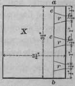
Cut both pieces as shown by Fig. 205. Taking one of the pieces, which will be called X, space1 and lay off on the reduced end surface lines as op, Fig. 206, using the try-square blade as indicated by the dotted outline. Next, produce oblique lines as gh, shown in the same figure, and cut the mortises marked r.
With Y in the vise apply X, in which the mortises have already been cut, as shown by Fig. 207, so that points may be located along the exterior angle e' of Y, corresponding to the openings in X. Project these points (shown on line e'f', Fig. 208) from the exterior angle e', to the interior angle b', Fig. 207. Next apply X to Y, as shown by Fig. 209; from this position the points shown on the line a'i', Fig. 208, can be secured along the angle a'. These points, when connected, will give lines as gh, Y, Fig. 206. From these lines, project on the working-face lines as ij, down to the line d'k1. Cut out the portions marked r, and the dovetail is finished. It now remains to make a miter-joint between the two rectangular projections on X and Y. Set the bevel at a miter (an angle of 45 degrees) and scribe the dotted line e, Fig. 205, on each piece; then cut to line with a chisel. When the joint has been fitted, glue, and finish to dimensions.
Continue to:
My Books

