167. To Make A Pin (249). Part 3
Description
This section is from the book "Bench Work In Wood", by W. F. M. Goss. Also available from Amazon: Bench Work In Wood.
167. To Make A Pin (249). Part 3
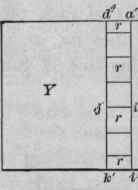
Fig. 206 Scale, 3" - l'

Elevation (Face A.).

End.
Elevation (Face A.).

End.
1 No dimensions are given for locating the lines similar to op, X, Fig. 206. They can be found by measuring the drawing, which, as indicated by the scale, is one-fourth the size of the piece it represents.
Fig. 207

Fig.208
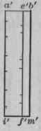
Fig. 209

176. If, instead of cutting out the first and last space of Y, one-half only is cut out, as shown by Fig. 210, the dividing line being on a miter, and, if the outside portions of X, m, m, Fig. 206, are cut away to a miter to correspond, the joint will appear as a plain miter-joint, instead of that shown by Fig. 203.
Fig. 210
Exercise No. 14. - Frame and Panel (246-248).
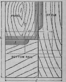
177. Fig. 211 shows a small panel door. The frame is made up of stiles and rails, which are fastened together by mortise-and-tenon joints; the spaces within the frame are filled by panels. The lower panel is simply a thin board screwed to the back of the frame. The upper panel is composed of narrow strips, which are inserted in a groove made in the frame for their reception. The front of the frame, around the lower panel, is chamfered, and around the upper panel is beaded. It is the purpose of this exercise to construct that portion of the door included within the rectangle abdc.
Three pieces of stock are required, each jointed to dimensions as follows: for the stile, 1 1/8" X 2 1/2" X 9"; for the rail, 1 1/8" X 4" X 6 1/2"; and for the panel 1/2" X 5" X 5 1/2". The finished work is shown by Fig. 212.
Fig. 211
Plan.

Elevation.
Fig. 212

Plan.
Elevation.
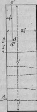
178. The mortise-and-tenon joint between the stile and rail, both in the size and position of its parts, is shown by Fig. 213. The width of the mortise and the tenon should be equal to the width of the 3/8" chisel.1 It will be noticed that the lines are so placed as to make the stile extend beyond the lower edge of the rail. This extension, or "horn," as it is called, is for the purpose of re-enforcing the end of the mortise during the fitting, - a recourse which must always be had when the mortise in the finished work closely approaches the end of the material. After all the jointing has been done, the horns may be cut off. Having laid off the necessary lines for cutting the mortise and the tenon, very light lines, as cd and c'd', Fig. 213, should be made on both stile and rail to guide in cutting the chamfers.
1 The nominal width of a chisel does not always agree with its actual width.
Fig. 213 Scale, 3"=1"

Side Of Rail.
Side Of Stile.

Edge A Of Stile.
Cut and fit the mortise and tenon, and then make both chamfers, as shown in the finished piece, Fig. 212.
179,. Short chamfers (222, 223) like these are best cut by use of the chisel, a spokeshave sometimes being used in finishing.
Long chamfers may be cut rapidly by the drawing-knife, which may be followed by the smooth-plane.
180. Before putting the joint together, enlarge the outside end of each mortise, as shown by a and b, Fig. 213, to make room for the wedges c, c, which, after the joint has been driven together, are to be dipped in glue and driven as indicated. This method of wedging forms a very strong joint (250, 251).
181. Round the edge of the panel on the bottom and side, as shown by a, Fig. 212, and fasten it to the back of the frame by two 1" No. 8 screws - one in the rail, and one, b, in the stile (258).
182. In inserting screws, the outside piece (in this case the panel) must be bored for each screw. The hole should be sufficiently large to allow the screw to pass through easily; and, if the wood is hard, it must be enlarged at the top, or "coun-terbored," to receive the head of the screw. The piece in which the screw holds (in this case the frame), if of soft wood, need not be bored unless there is danger that it may split, in which case a hole should be made, in diameter about two-thirds that of the screw. The necessity for a hole in hard wood depends largely on the proportions of the screw. A short, large-wired screw will stand almost any service, while a long slender one will frequently be twisted or broken under the strain necessary to drive it into wood which is only moderately hard.
Judgment must determine when the screw is driven sufficiently. The head must bed well into the wood; but there is danger that it may be forced so far as to "strip" the thread, and that, as a consequence, the screw will not hold (96, 98).
Never allow the screw-driver to slip from the slot of the screw while the latter is being driven.
Continue to:
My Books

