


Part III. Elements Of Wood Construction Carpentry. Continued
Description
This section is from the book "Bench Work In Wood", by W. F. M. Goss. Also available from Amazon: Bench Work In Wood.
Part III. Elements Of Wood Construction Carpentry. Continued
193. A Fished Joint in its simplest form is shown by Fig. 225, and is so called because of the two pieces marked A which are known as fish-pieces or fish-plates.
Fig.224
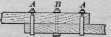
Fig.225

Fish-pieces may be of either wood or iron, and may be employed to form the fished joint shown in Fig. 225, or applied to more complicated joints to increase their strength.
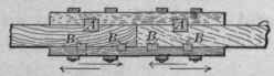
When subject to compressional stress a fished joint should have four plates, one on each face. When subject to tensional stress the plates, if of iron, may be indented, A, Fig. 226; or, if of hard wood, the ends may be tabled, B, Fig. 226, or keys inserted as shown by A and B, Fig. 227. Other things being equal, if the number of keys is doubled, the thickness of each may be diminished one-half without reducing the strength of the joint, since the total amount of abutting surface will remain the same.
Fig. 226
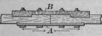
Fig.227
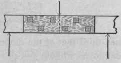
For transverse stress the fish-pieces should be on the sides of the joint, as shown by Fig. 228.
The bolts used for securing fish-pieces, or employed as fastenings for any joint, should be placed checker-wise, Fig. 228, so that no two will cut the same cross-section.
Fished joints are often used in heavy construction. By a suitable proportion of parts the joint can be made almost as strong as the timbers it connects.
194. Scarfed Joints are those in which the two timbers united are so cut and fitted as to make the joint uniform in size with the timbers. In determining the form of any scarf, the principles already given (191) should be adhered to as closely as possible. Some scarfs by their form are self-sustaining, but compared with the timbers they unite, are weak, and are seldom used unless strengthened by bolts, or by bolts and fish-pieces.
Fig. 228
Note
The student should observe carefully the position of the lines in the following representations of joints, so that he may clearly see the reasons for the different methods of construction. He should first look for the abutting surfaces, and then note their relation to the rest of the joint.
195. A scarfed joint for resisting compression is shown in its simplest form by Fig. 229. When strengthened by bolts and fish-pieces it forms an exceedingly good joint.
Fig. 229
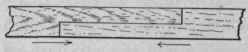
Fig. 230

196. A scarfed joint for resisting tension is shown by Fig. 230. The key A supplies the abutting surface to receive the strain tending to open the joint; in thickness it is equal to one-third that of the timber. In practice this joint is not often employed without fish-pieces. Fig. 231 shows a modification of Fig. 235 which will serve excellently for tensional stress.
Fig.231
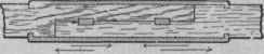
197. A scarfed joint for resisting transverse stresses is subject to compressional stress in its upper portion, and to tensional stress in its lower portion (190), and must, therefore, embody forms adapted to resisting both, as shown by Fig. 232. A single fish-piece is usually added to the lower side of the joint.
Fig. 232
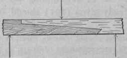
198. A scarfed joint for resisting tension and compression may be made as shown by Fig. 233; or, less complicated as shown by Fig. 234; or, more secure as shown by Fig. 235.
Fig. S33

Fig. 234

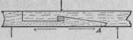
199. A scarfed joint for resisting tension and tranverse stress is sometimes made as illustrated by Fig. 236; but this form is not so good as the joint shown by Fig. 228, if in the latter case the fish-pieces are indented.
Fig. 235

Fig. 236
Joints connecting Timbers at Right Angles.
200. Halving, Fig. 237, forms a very simple joint, and when well fastened, a strong one. It is frequently employed.
Fig. 237
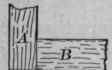
Plan.
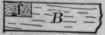
Elevation.
Fig. 238
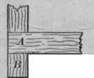
Plan.
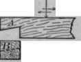
Elevation.
Fig. 239
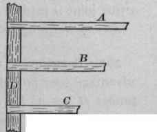
Plan.
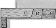
Elevation.
Beveled-halving, Fig. 238, is sometimes resorted to with the view of allowing the load imposed upon A in the direction of the arrow, to hold the joint together. Under ordinary circumstances this joint is likely to prove weak, because of a lack of material at the shoulder near the letter A.
Continue to:


My Books

