House Building. Part 3
Description
This section is from the book "Carpentry for Boys", by J. S. Zerbe. Also available from Amazon: Carpentry for Boys.
House Building. Part 3
The Roof
The pitch of the roof (Fig. 225) is what is called "third pitch," and the roof (Fig. 226) has a half pitch. A "third" pitch is determined as follows:
Roof Pitch
In Fig. 227 draw a vertical line (A) and join it by a horizontal line (B). Then strike a circle (C) and step it off into three parts. The line (D), which intersects the first mark (E) and the angle of the lines (A, B), is the pitch.
In Fig. 228 the line A is struck at 15 degrees, which is halfway between lines B and C, and it is, therefore, termed "half-pitch."
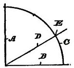 | 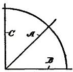 |
Fig. 227. | Fig. 228. |
Thus, we have made the ground plans, the elevations and the roofs as simple as possible. Let us proceed next with the details of the building.
The Foundation
This may be of brick, stone or concrete, and its dimensions should be at least 1½ inches further out than the sill.
The Sills
We are going to build what is called a "balloon frame"; and, first, we put down the sills, which will be a course of 2" × 6", or 2" × 8" joists, as in Fig. 229.
The Flooring Joist
The flooring joists (A) are then put down (Fig. 230). These should extend clear across the house from side to side, if possible, or, if the plan is too wide, they should be lapped at the middle wall and spiked together. The ends should extend out flush with the outer margins of the sills, as shown, but in putting down the first and last sill, space must be left along the sides of the joist of sufficient width to place the studding.
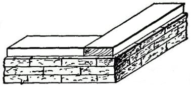 Fig. 229.
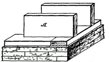 Fig. 230.
The Studding
The next step is to put the studding into position. 4" × 4" must be used for corners and at the sides of door and window openings. 4" × 6" may be used at corners, if preferred. Consult your plan and see where the openings are for doors and windows. Measure the widths of the door and window frames, and make a measuring stick for this purpose. You must leave at least one-half inch clearance for the window or door frame, so as to give sufficient room to plumb and set the frame.
Setting Up
First set up the corner posts, plumbing and bracing them. Cut a top plate for each side you are working on.
 Fig. 231.
The Plate
As it will be necessary in our job to use two or more lengths of 2" × 4" scantling for the plate, it will be necessary to join them together. Do this with a lap-and-butt joint (Fig. 231).
Then set up the 4" × 4" posts for the sides of the doors and windows, and for the partition walls.
The plate should be laid down on the sill, and marked with a pencil for every scantling to correspond with the sill markings. The plate is then put on and spiked to the 4" × 4" posts.
Continue to:
My Books

