The Tail-Stock, The Carriage, The Apron, Etc. Part 6
Description
This section is from the book "Lathe Design, Construction And Operation, With Practical Examples Of The Lathe Work", by Oscar E. Perrigo. Also available from Amazon: Lathe Design: Construction And Operation.
The Tail-Stock, The Carriage, The Apron, Etc. Part 6
The R. K. Le Blond taper attachment is shown in Fig. 117. The slide supporting bracket A is attached to a dovetail formed upon or attached to, the bed. Upon it is swiveled the guiding bar B, upon which is fitted the sliding block C, pivotally connected with the compound rest shoe D, by means of the block E and connection F.

Fig. 117. - Taper Attachment built by the R. K. Le Blond Machine Tool Company.
This taper attachment is of new design, and is very rigid. It is changed from straight to taper work by simply removing a taper pin from one hole to another. The cross-feed nut is never disconnected and the compound rest can be moved by the screw when turning both straight and taper work.
When extra heavy work is done the compound rest can be clamped to the taper attachment by a brace. By this arrangement all thrust is relieved from the screw, insuring greater accuracy. The guiding bar is graduated to taper per foot and is clamped in position by two T-slot bolts. A graduated screw adjustment is provided for accurately setting the bar.
Figure 118 shows the Lodge & Shipley taper attachment. It is constructed in a similar manner to that made by the F. E. Reed Company, as will be seen by the engravings of the two devices.
It is supported by the carriage, and the supporting bar upon which the inclined guide-bar A rests is secured against longitudinal movement by a rod D and bracket E, the latter clamped to the bed the same as in Reed's device.
The taper attachment is extremely simple, and composed of less parts than any in the market. In operation it is changed from straight to taper by tightening or releasing one screw on the dog. When attached for taper work the sliding shoe connects directly with the tool-rest and not with the screw, making its operation instantaneous. The nut is made to release and slide in a groove. The stud for the sliding shoe also engages into a groove, and to attach or detach requires nothing more or less than the releasing of one screw and tightening another, or vice versa.

Fig. 118 - Taper Attachment built by the Lodge & Shipley Machine Tool Company.
The cross-feed nut cannot fall over as in ordinary taper attachment when in use, because it is never disconnected. The bolt simply slides in a slot in the compound rest slide.
Figure 119 shows the taper attachment made by the Hamilton Machine Tool Company. Like that made by the R. K. Le Blond Machine Tool Company, this has its supporting bracket carried upon a slide formed upon or attached to the bed. It is thereby rendered very rigid and substantial. The swiveling of the inclined guiding bar is similar to those already described, and the attachment of the connecting block to the cross-feed screw is easily understood by reference to the engraving in which it will be seen that the end of this block passes through the bracket attached to the rear of the carriage. The sliding block runs in a dovetail in the inclined guide-bar instead of on a square raised rib on top of it.

Fig. 119. - Taper Attachment built by the Hamilton Machine Tool Company.
This dovetail form is not at all necessary, as a square form is as good, if not better, and much more economical. There is no tendency to lift the block that would make the dovetail form advisable. The Hendey-Norton Taper attachment is shown in Fig. 120.

Fig. 120. - Taper Attachment built by the Hendey Machine Company.
It is supported by the carriage as in the Reed and the Lodge & Shipley designs, and travels with it and is therefore always ready for use. All operations necessary to use the attachment are made from the front of the carriage, and consist of first setting the taper bar to any desired degree, binding the sliding bar clamp to the back V, loosening the post screw at the end of the carriage arm which releases the cross-feed screw connecting block, and clamping the connecting link onto the taper-bar slide by means of the binding handle. The top link and the binding bolt, which is fitted to a reamed hole in the head of the block, furnish a double connection (and one that is absolutely rigid) between the two slides, preventing any back-lash.
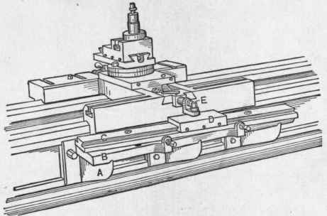
Fig. 121. - Taper Attachment built by the New Haven Manufacturing Company.
Figure 121 shows the taper attachment as made by the New Haven Manufacturing Company. The supporting bracket is adapted to travel in an upper and lower groove planed in projecting ribs on the back of the bed, thus rendering the support very rigid. The plate B is heavy and rigid and supports the swiveling guide-bar C, upon which slides the block D. In the later development of this device the dovetail is replaced by a square projecting rib. There is also an improvement in the connection E with the cross-feed screw, consisting of a heavy flat bar attached to the rear of the compound rest shoe and sliding through a strong and rigid guide block. Its rear end is pivotally connected with the block D, making a very accurate and rigid design.
In all these attachments making use of the cross-feed screw as an adjusting member, it must be so arranged as to be detachable from its front bearing, or permitted to slide through it so that the inclined movement of the block on the guide-bar may gradually work the compound rest forward and back to form the taper as the cut proceeds.

Fig. 122. - Plan of the Bradford Taper Attachment.
Figure 122 is a plan of the Bradford taper attachment, and Fig. 123 is a cross section of the same device. It is of the type of carriagesuspended devices similar to several heretofore shown and described.

Fig. 123. - Cross Section of the Bradford Taper Attachment.
From the accompanying sectional view it will be seen that the rear end of the cross-feed screw is held by collars and journaled in a bearing, which is bolted to a bar connecting it with the sliding shoe on the inclined slide, so that the screw always moves with the bar and carries the compound rest with it.
The tool is controlled by the screw at all times without interfering with the handle, the end of the screw telescoping into the sleeve on which is the pinion governing the power feed. Where it telescopes it is splined, and so the screw is under control of the operator, irrespective of the position of the tool due to the taper bar. When turning tapers the lower slide of the compound rest should be tightly clamped to the bar by the square head screw, shown in cut. Consequently there is no disconnecting of any of the parts when engaging or disengaging the attachment. Simply tightening the dog to the ways brings the attachment into service, and loosening the same disengages the attachment, leaving the lathe in proper shape for straight work; and in neither case does the use of the attachment interfere in the slightest degree with the full and complete use of the compound rest, should it be desired to face off a piece the full swing of the lathe.
The construction further makes the attachment of exceptional value on lathes of extra length, in that it is available the full distance between centers by reason of its being bolted to, and traveling with, the lathe carriage.
Continue to:
My Books

