


Grooving Planes, Etc. Part 2
Description
This section is from the book "Our Workshop", by Anonymous. Also available from Amazon: Our Workshop.
Grooving Planes, Etc. Part 2

Fig. 66.
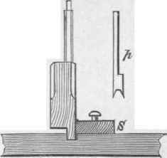
Fig. 67.
It is evident that the distance of the groove from the edge of the work against which the fence rubs, is limited to the length of the transverse stems, s, s, fig. 66. Frequently a groove, or perhaps several, are required much further from the margin of the work than the range of the fence will permit.
A simpler form of grooving-plane must be employed in this case, and one in which the fence forms no part of the structure.
Fig. 67 represents a grooving-plane applicable for making grooves at any distance, however remote from the edge of the work. A narrow strip of wood (s) or a straight edge is temporarily nailed down to guide the tool while cutting the groove. As the plane is often used across the grain, it must be furnished with a scoring-point, in fact with two - one for each side of the groove. One scoring-point will suffice if it be divided at the extremity into two teeth, as shown separately at page 129. The grooves formed by this plane are generally intended for receiving the ends of shelves; consequently their sides are the more important parts, and the bottoms may be sufficiently well worked by an iron fixed square across the stock. The stop must still be retained with the thumb-screw adjustment; or the less costly and less certain arrangement of a piece of boxwood stiffly fitted into the stock may be substituted for it.

Fig. 68.

Fig. 69.

Fig. 70.
Boards for partitions and similar works could not be properly united by simply glueing them edge to edge. The split-deal or match planes (figs. 68 and 69) are therefore used by carpenters to form the groove and tongue-joint, which is shown finished in fig. 70. These are simply grooving-planes for working with the grain : the irons are placed square in the stocks, and the scoring-points are omitted; the stops are not required, as the tool is worked until some part of the stock rests on the work. These planes are made in pairs, and must be used only for "stuff" of the thickness for which they are intended, otherwise the centre of the irons will not correspond with the centre of the work, and the groove and tongue will not be in the middle of the edge of the board.
Sometimes it is necessary to plane the perpendicular sides of grooves, etc, independently of the bottoms, to widen them sufficiently to admit a thicker shelf, etc. The rabbet and grooving-planes would be inconvenient, even if they could be used; consequently another tool, which will cut on one side only, must be employed. The side rebate-plane is shown in elevation in fig. 71. It will be seen, by referring to fig. 73, that the left-hand side s of the stock is bevilled, thus reducing the part which is the sole in other planes to a narrow edge, the sole being transferred to the side a b; the edge of the cutter is seen at c, fig. 71. The iron is fixed obliquely in the stock, as may be seen at f, fig. 72, which is a plan of the tool. The iron is similar in shape to the stock at s, fig. 73, and is placed in it obliquely, to give the side edge the necessary prominence, and vertically, because the lower extremity is no longer required to operate. These planes are made in pairs, or right and left-handed, so that they may be conveniently employed in situations where the work cannot be turned round to bring the opposite edge toward the workman.

Fig. 71.

Fig. 72.

Fig. 73.
Moulding-planes are not now much employed, as mouldings can be produced by machinery at a much cheaper rate than by hand labour. The irons of moulding-planes have the exact but reversed outline of the required moulding imparted to their edges, so that the hollow or concave parts leave mouldings in relief, while the convex portions, by removing the material, make corresponding depressions.
The joiner uses moulding-planes of a simple and neat design for window-frames or sashes, and for the sash-bars between which the panes of glass are introduced. The work must be truly planed to its proper size before the moulding-plane can be employed, as this tool, like the grooving-planes, requires true surfaces to work upon.
The sticking-board, S S, fig. 74, is of great assistance when working, or, technically speaking, sticking a moulding on very slight work, like the sash-bar, b b. The sash-bar is held by jamming the tongue that is formed for holding the glass into the groove g, in the strip d d, which latter is secured to the bed S S. The moulding not being made parallel to the surface of the board, but obliquely, as may be seen by the slanting position of the plane P, the work must first be roughly bevilled by the jack-plane to lessen the labour of sticking the moulding.
The moulding-plane is provided with a fence and a stop solid with the stock, as they do not require adjustment, as in the fillister, etc. When the plane is applied to the work, the fence o, fig. 74, is placed against the edge, and is kept in contact with it until the moulding is finished.

Fig. 74.
The iron continues to remove the material till the stop n rests upon the surface of either the strip d, or the plain part of the sash-bar. On the completion of the first side, the sash-bar must be turned over and re fixed. The finished side being bevilled, it cannot rest fairly on the bed, S S, therefore small wedges of wood or packing-pieces must be inserted between it and the bed to support the bar and relieve the tongue of the undue strain, which otherwise it would be required to sustain, while we were "sticking" the second side of the bar.
Continue to:


My Books

