Bevels And Harks
Description
This section is from the "The Elements Of Wood Ship Construction" book, by W. H. Curtis. Also see Amazon: The Elements Of Wood Ship Construction.
Bevels And Harks
Bevels are marked in degrees followed by letter "U" for under and "S" for standing; "2« U" means two and one-half degrees under, and "3 S" means three degrees standing. Where there is no bevel, that is, where the timber is to be sawn square, it is marked with a cross in a circle thus ®
The principles involved in lifting frame bevels from the floor are very simple and should be understood by all ship carpenters, as they are frequently of use in operations other than framing.
Figure 46 shows a section and part of the plan of two frames. On the loft floor body plan only the lines M-M and N-N appear and the problem is to determine the proper bevel in degrees for the frame by measuring the distance between these lines. In this figure, A represents the distance between centers of frames, B the distance at one point between the lines M-M and N-N, and X the angle which it is desired to find, by measuring the distance B.
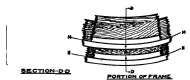
Figure 46.
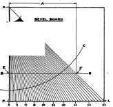
Figure 47.
Figure 48. Level Stick.
Frame Bevels, Bevelboard And Stick.
The first step is to construct a bevel board as shown in Fig. 47 as follows: Build up a square board having sides somewhat greater than the distance between frame centers. The board should have a smooth top, and be perfectly square, or have a perfect square scribed upon it, in which latter case the scribed square is considered as the extent of the board.
Then from the corner O draw a straight line to the corner L. This line will make an angle of 45 degrees with the side O-P. Next, with O as the center, draw any arc C-C, preferably with as large a radius as can be used on the board. Divide this arc between the lines O-L and O-P into 45 equal parts. Then each part represents a degree. Through each degree mark on the arc C-C draw a straight line from the center O extended to the side P-L.
The lines should then be numbered from 0 to 45, beginning with the side O-P as 0.
The next step is to lay out the bevel stick. Each different distance between frame centers will call for a different bevel stick, but they may all be taken off the same bevel board. In this case the distance between the frame centers is represented by the letter A, which represents the actual distance between the frames of the ship where bevels are desired.
Measure in from O on the top of the board, the distance A, and draw a line parallel to the side O-P, or square with the top, until it meets the line O-L at the point F. Through F draw line S-S parallel to the top of the board and square with the side O-P. This line between the points F and E will be the same length as the distance between the frame centers, and the points where the degree lines cross it are transferred to the bevel stick shown in Fig. 48, and numbered from 0 to 45.
Now, if the distance B be measured with this stick the degrees of the angle X may be read directly from the stick. If the lines M-M and N-N are very close together the bevel will be small, if far apart the bevel will be large, and if they are coincident, that is one over the other so that they appear as the same line, there will be no bevel and the timbers will be sawn square.
Continue to:
My Books

