Pneumatic Tools
Description
This section is from the book "Workshop Receipts For Manufacturers And Scientific Amateurs. Supplement Aluminium To Wireless", by The Chemical Publishing Co.. Also available from Amazon: Workshop Receipts For Manufacturers And Scientific Amateurs.
Pneumatic Tools
These may be divided into two types, those having purely a reciprocating action, and those having a rotary action. Of the former the most commonly used tools are hammers, which may again be used for different purposes, such as riveting, chipping and caulking. Fig. 169 shows a section through a Boyer chipping hammer. It being understood that the shank of a chipping tool slides in and well fits the circular space at the lower end of the hammer. The tool being supplied with compressed air at from 80 to 100 lbs. pressure, and the tool being held well up to its work, the action is as follows. The throttle lever in the handle is depressed by the thumb, the air enters the hammer, and the piston in the centre makes rapid to and fro movements along the hammer bore, so striking rapid blows upon the shank of the chipping tool. These blows may range from 1,600 to 3,000 per minute, depending upon the size etc. of the hammer. In the hammer interior, near the handle is the valve in the form of a short cylinder of peculiar section, and which has a very short axial movement along the bore. In a down stroke of the piston the valve has been at the handle end of its travel, and has allowed air to pass on to the end of the piston. This then travels down the hammer with air pressure behind it. When it is nearing the end of its stroke a port in the bore of space in which it travels is uncovered and air passes from the main supply around the recess shown in the body of the piston, and into a port which is now uncovered by the piston, and so up to the underside of the air valve, which it throws up to its first position. At this time the back end of the piston is thrown open to the exhaust. Also the valve now being up, air is admitted into the long recess running from the valve chamber to the bottom of the piston travel, this returns the piston to the handle end of its travel again, and while doing so the piston uncovers the port shown on the upper part of Fig. 169 so releasing the air pressure on the underside of the valve, and admitting this air also to exhaust, the whole series then again repeats, and so on, until the air throttle is released from thumb pressure. From the above description of the hammer working, and consideration of the design, it is clear that accurate workmanship and first class material are required, and this can be depended upon in all well known makes, so much is this the case that pneumatic tools are now very extensively used in very many large works. Due care is, of course, given to them, the air is passed through sieves to remove any foreign matter, etc., and after use they have a charge of suitable oil blown through them. The varieties of outward design, weights, and number of blows per minute is considerable, but the general principle of working is as described above. On no account whatever should a pneumatic hammer be operated unless it is actually doing work, as otherwise serious damage may result, as the piston is likely to hit the front of the cylinder, and in riveting hammers where there is no retaining wall at the bottom of the piston bore the piston and snap may be shot out of the hammer. See Fig. 170, which shows a Boyer long stroke riveting hammer, the rivet snap is shown at the end of the bore, and held therein by a spring clip.
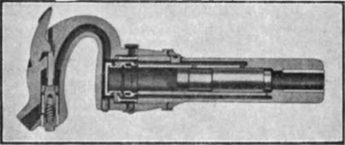
Fig. 163.

Fig. 170.
Pneumatic drills obtain their motion by means of small air motors. Fig. 171 shows a section of the Red Giant drill from which it will be seen that it has two double acting cylinders. The various parts are :
1. ;Three-throw crankshaft, with ball bearings.
2. ;Valve moved by eccentric 3.
3. ;Eccentric, an integral part of crank shaft.
4. ;Packing glands.
5. ;Connecting rods.
6. ;Crosshead and guides.
7. ;Three unit casting.
8. ;Feed screw or grip handle.
interchangeable.
9. ;Outside spindle.
The action of the drill is fairly obvious, it working or acting just as any other two-cylinder double-acting engine or motor. Fig. 172 shows a section of a Single Stage Steam Driven Air Compressor, the air compressor being water jacketed with large special design air valves. There are many other applications of rotary tool work, especially to the use of grinding machines, etc., giving a portable, high speed tool in a compact form. It is, of course, important to avoid air leakage anywhere on the line, and the Capill hose coupling is shown in Fig. 173.
It is important to note that the connection is made by slipping the coupling nut and sleeve on to the ends of the hose, allowing the latter to project at least |in. through the sleeve, then insert the cone end of the screwed union, pressing same well into the hose and screwing up the coupling nut by hand, which is all that is necessary, no spanner being required.
The great advantage of this coupling is its simplicity ; it requires no washers or clamps, and is self-adjusting, as the joint is made on the face of the cone by the sleeve, as illustrated above.
Care Of Pneumatic Tools
The results obtained from Pneumatic Tools depend in a large measure on the treatment they receive, both in service and when in the tool store.
A clean supply of compressed air is the first essential ; see that the suction pipe on the compressor is not placed where it can draw dust or dirt of any description, also that the hose pipe, when disconnected from the tool, is not laid down where grit may lodge in the connector and be subsequently blown into the machine ; this is a frequent source of trouble, therefore blow air through the hose pipe before connecting up ; this will remove moisture as well as dust.
Continue to:
My Books

