Wires Run Exposed On Insulators
Description
This section is from the book "Cyclopedia Of Architecture, Carpentry, And Building", by James C. et al. Also available from Amazon: Cyclopedia Of Architecture, Carpentry And Building.
Wires Run Exposed On Insulators
This method of wiring has the advantages of cheapness,durability, and accessibility.
Cheapness. The relative cost of this method of wiring as compared with that of the concealed conduit system, is about fifty per cent of the latter if rubber-covered conductors are used, and about forty per cent of the latter if weatherproof slow-burning conductors are used. As the Rules of the Fire Underwriters allow the use of weatherproof slow-burning conductors in dry places, considerable saving may be effected by this method of wiring, provided there is no objection to it from the standpoint of appearance, and also provided that it is not liable to mechanical injury or disarrangement.

Fig. 18. Large Feeders Run Exposed on Insulators.
Durability. It is a well-known fact that rubber insulation has a relatively short life. Inasmuch as in this method of wiring, the insulation does not depend upon the insulation of the conductors, but on the insulators themselves, which are of glass or porcelain, this system is much more desirable than any of the other methods. Of course, if the conductors are mechanically injured, or the insulators broken, the insulation of the system is reduced; but there is no gradual deterioration as there is in the case of other methods of wiring, where rubber is depended upon for insulation. This is especially true in hot places, particularly where the temperature is 120oF. or above. For
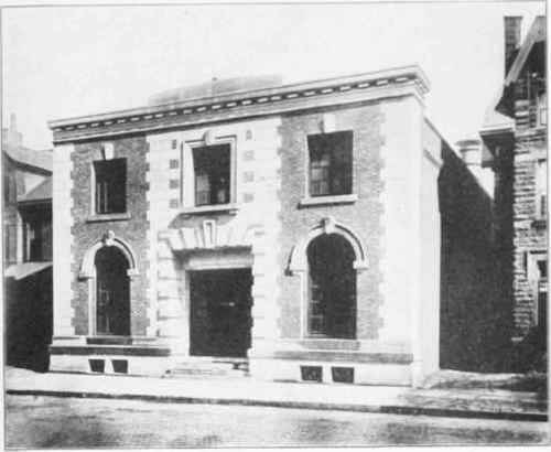
Dodge Street Substation.
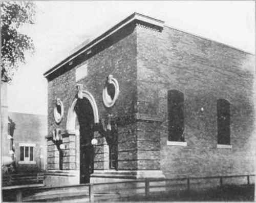
SUBSTATIONS OF THE CLEVELAND ELECTRIC ILLUMINATING COMPANY. CLEVELAND, OHIO.
Watterson & Schneider, Architects, Cleveland, Ohio.
Such cases, the weatherproof slow-burning conductors on porcelain or glass insulators are especially recommended.
Accessibility. The conductors being run exposed, they may be readily repaired or removed, or connections may be made to the same.
This method of wiring is especially recommended for mills, factories, and for large or long feeder conductors.
Fig. 18 shows examples of exposed large feeder conductors, installed in the New York Life Insurance Building, New York City. For small conductors, up to say No. 6 B. & S. Gauge each, porcelain cleats may be used to support one, two, or three conductors, provided the distance between the conductors is at least 2 1/2 inches in a two-wire system, and 2 1/2 inches between the two outside conductors in a three-wire system where the potential between the outside conductors is not over 300 volts. The cleat must hold the wire at least one-half inch from the surface to which the cleat is fastened; and in damp places the wire must be held at least one inch from the surface wired over. For larger conductors, from No. 6 to No. 4/ 0 B. & S. Gauge, it is usual to use single porcelain cleats or knobs. Figs. 19 and 20 show a good form of two-wire cleat and single-wire cleat, respectively.
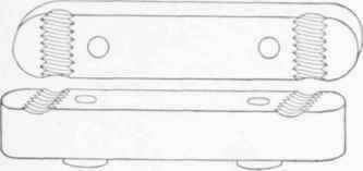
Fig. 19. Two-Wire Cleat.
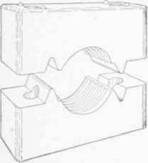
Fig. 20. One-Wire Cleat.
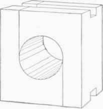
Fig. 21. Porcelain Insulator for.
Large Conductors.
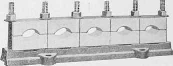
Fig. 22. Iron Rack and Insulators for Large Conductors. Courtesy of General Electric Co., Schenectady, N. Y.
For large feeder or main conductors from No. 4/0 B. & S. Gauge upward, a more substantial form of porcelain insulator should be used, such as shown in Fig. 21. These insulators are held in iron racks or angle-iron frames, of which two forms are shown in Figs. 22 and 23. The latter form of rack is particularly desirable for heavy conductors and where a number of conductors are run together. In this form of rack, any length of conductor can be removed without disturbing the other conductors.
As a rule, the porcelain insulators should be placed not more than 4 1/2 feet apart; and if the wires are liable to be disturbed, the distance between supports should be shortened, particularly for small conductors. If the beams are so far apart that supports cannot be obtained every 4 1/2 feet, it is necessary to provide a running board as shown in Fig. 24, to which the porcelain cleats and knobs can be fastened. Figs. 25 and 26 show two methods of supporting small conductors, For conductors of No. 8 B. & S.
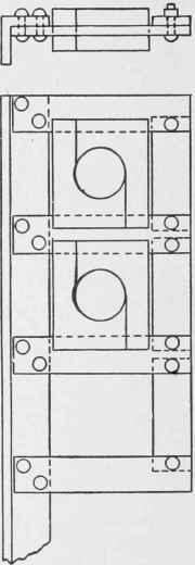
Fig. 23. Elevation and Plan of Insulators Held in Angle-Iron Frames.
Gauge, or over, it is not necessary to break around the beams, provided they are not liable to be disturbed; but the supports may be placed on each beam.
Where the distance between the supports, however, is greater than 4 1/2 feet, it is usually necessary to provide intermediate supports, as shown in Fig. 27, or else to provide a running-board. Another method which may be used, where beams are further than 4 1/2 feet apart, is to run a main along the wall at right angles to the beams, and to have the individual circuits run between and parallel to the beams.
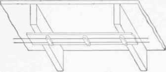
Fig. 24. Insulators Mounted on Running Board across Wide-Spaced Beams.
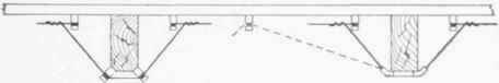
Fig. 25. Method of Supporting Small Conductors.
Continue to:
My Books

