End Mills
Description
This section is from the book "Modern Shop Practice", by Howard Monroe Raymond. Also available from Amazon: Modern Shop Practice.
End Mills
This form of milling machine cutter, Fig. 235, is familiarly known as a shank mill, on account of the shank, which in small milling cutters fits into a collet. This collet in turn fits the hole in the spindle of the milling machine; the collet is used to save stock in making the cutters, as otherwise it would be necessary to use steel large enough to make a shank the size of the hole in the spindle of the milling machine.
The cutter shown in the figure is what is termed a left-hand mill; if the teeth run in the opposite direction, it is called a right-hand mill.
In making a shank, or end mill, of the form shown, stock should be selected enough larger than the cutting end to allow of turning off the decarbonized surface of the steel. After the ends have been faced to length, and the roughing chip turned, the cutting end can be run in the steady rest of the lathe, and the center cut away, or recessed, as shown at the end of the mill. The blank should be re-centered and countersunk, to furnish a center to use in turning the mill to size and shape. The object in cutting the center out as shown is to furnish a cavity for the angular cutter used in cutting the teeth on the end of the mill. Without the recess, it would be impossible to grind satisfactorily.

Fig. 235. Straight Flute Left-Hand End Mill Courtesy of Becker Milling Machine Company, Hyde Park, Massachusettet.
After re-centering the recessed end, the opposite end should be turned to size and milled to thickness, which should be a trifle- 1/32 inch-less than the width of the center key slot in the collet. The taper shank should be turned enough larger than finish size to allow for grinding after the milling cutter is hardened; the cutter end should be turned .010 inch larger than the required diameter; the portion just back of the cutters should be turned 1/32 inch smaller than the large end of the shank, or to dimensions, if any are given on the drawings.

Fig. 236. Cutter with Weak Teeth.

Fig. 237. Cutter with Well-Formed Teeth.

Fig. 238. Cutter with Especially Strong Teeth.
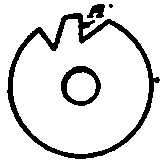
Fig. 239. Method of Cutting Strong Teeth.
In order to insure teeth strong enough to resist the strain of cutting, an angular mill should be selected that will give the required shape. In Fig. 236 is shown a form of cutter tooth too weak for actual service, the result of using an angular cutter with a cutting face forming an angle that is too acute with the side. Fig. 237 illustrates a cutter whose teeth are strong, yet deep enough to be practical; these teeth were cut with an angular mill of smaller angle. Fig. 238 represents a cutter whose teeth were cut with the same cutter used for Fig. 236. The teeth were cut to the required depth first, but this of course left them too thick at the cutting edges A, Fig. 239, and the index head was turned sufficiently to cut the teeth as shown at A, Fig. 238.
After the teeth around the circumference of the mill have been cut, the mill should be placed in the collet, and the collet put in the spindle hole in the spiral head to cut the teeth on the end. When the teeth on the end of the mill are being cut, the spiral head is turned until the cutter is in a horizontal position. The angular cutter used should not have a very acute angle, or the teeth will be weak.

Fig. 240. Spiral End Mill Courtesy of Becker Milling Machine Company, Hyde Park, Massachusetts.
An 80-degree angular milling cutter will be satisfactory for most work.
Continue to:
My Books

