Engine Cylinder
Description
This section is from the book "Modern Shop Practice", by Howard Monroe Raymond. Also available from Amazon: Modern Shop Practice.
Engine Cylinder
The slide-valve engine is built in a great variety of forms. Fig. 209 represents a sectional view of the cylinder of a very cornmon type. At e Fig. 210, we have a cross-section through the steam chest and exhaust port at A B; and at F, a cross section at 0 1) through the steam port.
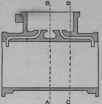
Fig. 209.
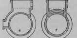
Fig. 210.
When the cylinder is small (ten inches or under in diameter) the pattern is usually built up solid, but if more than ten or twelve inches in diameter it should be built of staves, as shown in Fig. 211.
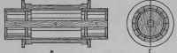
Fig. 211.
When the size is thirty inches or over, a. loam mould is usually made as will be fully described in the section on Foundry Work.
The size limit, however, varies greatly in different foundries. The construction of the pattern is illustrated in Fig. 211, and needs no description here, it being the same as already given for Fig. 207. The flanges, however, should be built up of segments of two or three layers each as shown in Fig. 212. After gluing up to the necessary thickness to make the flange, it is sawed in two halves, jointed and carefully centered on a woollen chuck and turned to the dimensions required.

Fig. 212.
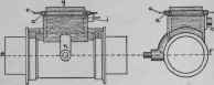
Fig. 213.
The centering must be done with accuracy, or one half of the flange, ring will be larger than the other. The steam chest is next built and fitted centrally on the upper half of the cylinder pattern as in Fig. 213. The projections a, a, which give the extra width of metal for the bolts of the chest cover are left loose, being kept in place by long wires or dowel pins as shown at c, c, 80 that they can be withdrawn separately from the mould after the main part of the pattern has been taken from the sand. These four strips should be recessed into the corners of the chest one quarter inch, as shown by the dotted lines, to prevent them from being rammed out of place after the dowel pins are taken out. The boss i for the valve-rod stuffing bos, and also the boss k around the steam-pipe opening, must be loose so as to be taken out of the mould after the pattern has been removed.
Fig. 21*.
The pieces o, o, at each end of the steam chest, which form a thickness of metal over the steam ports, are next fitted in place, as also the exhaust passage n which must be parted on the line of parting of the two halves of the cylinder pattern.
The main core box for the cylinder is made in the same way as has been already described for Fig. 208. The steam-chest core box is shown in Fig. 214, in which Pisa side view, one side of the box being removed to show the valve seat v, and the core prints a-, s, and y, which form recesses in the core, into which the upper ends of the two steam inlet cores, and the central exhaust passage core are placed. Q is an end view of the box with one end removed, and R is a view looking into the box from above.
For the core forming the exhaust passage, two half core boxes, one right and one left, will be necessary. One half of this bos is illustrated at S. Fig. 215. as also a sectional view at T. The dotted lines show the manner in which the passage is widened to retain the full size of the opening throughout.
Fig. 215.
Fig. 216.
Only one core bos will be needed for the two steam ports. Three views of the box are given in Fig. 216. At G one side is removed, giving a side view of the construction of the box. H shows a cross section through 6 with the end u removed, and F is a view from above. The core is swept off on the upper side for the length of c c, and the bar e e as well as the end u must be movable so that the core can be taken from the bos. Both ends of the core change from circular in to straight parts just at the entering of the cylinder, and at the entering of the steam chest.
The entire set of patterns are simple and easy of construction, if carefully made drawings are furnished to work from: the time and labor required, depending entirely upon the size of the cylinder.

6-INCH MOULDING MACHINE. H. B. Smith Machine Co.
These blocks are fastened by dowels, loosely, to the main part of the core box, and after the core has been rammed up, the whole box and core is turned over on its face and the main part of the box is lifted off, after which the two loose blocks a and a can be drawn away endwise and the block b can also be lifted out with ease.
Continue to:
My Books

