Pipe Connections
Description
This section is from the book "Modern Shop Practice", by Howard Monroe Raymond. Also available from Amazon: Modern Shop Practice.
Pipe Connections
Many patterns which at first may seem to be quite formidante. will, after a little study, resolve themselves into a few very simple parts, nearly all the work for which may be done in the lathe. Of this the tee pipe connection shown in Fig. 184, is a good illustration.
A sectional view of the casting threaded and having a pipe screwed into the right-hand end, is shown in Fig. 185. as illustrated in Fig. 188. The preparation of the wood for this pattern is similar to that described for the pattern of the brass bearing. Fig. 150; the two halves having the necessary dowel pins inserted, and glued together at the extreme ends only.

When there is not time for the glue to dry, all such parted work may be held together while being turned, by having staples driven into the ends as shown in Fig. 188. Indeed, for all large and heavy work this method is to be preferred; two, and even four, staples being used in each end as the size of the work may demand. When the turning is completed, it is only necessary to cut a V-shnped Opening into the two halves of a, into which the part f is fitted and glued. When the glue has set and is sufficiently dry, the joint may be further strengthened by nailing, or by inserting and screwing a thin metal connecting plate flush with the parting side of each half of the pattern. This, however, will be necessary only when patterns are large and heavy, or when unusual strength is required.
The core box for this pattern, as will bo seen in Fig. 189, is the usual half box and is made by working out the box in one piece, long enough to make the two parts a and b. The two parts are united by cutting a V-shaped opening in the part a and fitting b into it in the same way as described for the pattern. The whole is then glued and screwed to the board e, and the two triangular blocks d and d are glued in the angles to add strength to the completed box. In case the pattern is for a very small pipe, \\ inches or under, the part b may be abutted against the side of a, as shown by the dotted line, and the side of a at e cut away to the same curve as b, giving the same results ;is in the former method.

Fig. 185.

Fig. 186.
The pattern for the 2-ineh elbow, Fig. 190, is another illustration of how such work may be simplified, and time saved, by doing the greater part of the work in the lathe.
As these elbows are usually cast in large numbers, the pattern should be made double as shown in ' Fig. 191. To construct the double pattern, a ring is first turned like Fig. 192, a cross-section of which is a semicircle as shown in the lower right-hand corner of the drawing. This ring is cut into quarters, and the four pieces e, e, e and e make the quarter turns for the two halves of the double pattern.
Fig. 187.
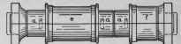
Fig. 188.
The ends, including the core prints and connecting tenons, are turned in one piece as shown in Fig. 193, the stock for which is prepared, with the inserted dowel pins all in position in the same manner as described for the lee pattern, Fig. 188. The quarters, e, e, e and e are clamped together two and two, and the ends carefully bored to receive the tenons which are then glued in position and further strengthened by a wood screw as shown in Fig. 101.

Fig. 189.

Fig. 190.
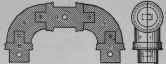
Fig. 191.
In Fig. 194, the core box for this double pattern is shown, and as will be seen the most difficult part of the work can be done in the lathe. Fig. 195 shows two pieces jointed and clamped together which must be screwed to the face-plate of the lathe and turned out to make the two corners c and c. The three straight parts d, d and d are worked out in one long piece and afterwards cut to the required lengths, after which the five pieces are glued and screwed to the board a. The ends e, e are next put on and the required half core box is complete.

Fig. 192.
Fig. l93.
Another reason why the pattern for pipe elbows should be made double is that otherwise the core prints would require to be made of great length in order to balance, sustain, and keep the heavy core in position; the tendency being to sag in the middle, or float on the molten iron, and thus make the upper side of the casting too thin, all of which is avoided in the double pattern.

Fig. 194.
A pattern for the return bend, Fig. 1%, can be built up and constructed in the same manner as described for the elbow; the semicircular returns, not only for the pattern, but also for the core box, being turned in the lathe, together with the ends and core prints for the pattern. As there will be no middle support for the core in this case, the core prints must bo made, as shown in the half pattern. Fig. 197, of sufficient length to balance the heavy semicircular core, and also to keep it in its true position in the mould.
The small wood lathe chuck, a vertical section of which is shown in Fig. 198, will serve as a simple illustration of the long core print and balanced core. The casting must be counter cored; that is, the cored opening must be enlarged at the forward end, adding to the size and weight of that end of the core, which, as will be seen, has no support except that afforded by the extra length of the core at the opposite end. The pattern for this chuck is shown in Fig. 199, and the core print must have a length at least twice as great as the depth of the hole in the chuck. The core box is shown in Fig. 200. When pipes or cylinders are of moderate size with deep flanges for bolting together (Fig. 201), the flanges for the pattern are turned out of a separate disc as shown in Fig. 202, and firmly glued and nailed on over the core prints and against the ends of the main body of the pattern; the core print being made of sufficient length to receive the flange. A recess is sometimes turned in the inside end of the core print to receive the inner edge of the flange as shown in Fig. 203, and into which it is fitted, thus adding greatly to the strength of the joint.
Fig. 195.

Fig. 196.

Fig. 197.

Fig. 198.

Fig. 199.
The flanges should be made by gluing up three pieces and crossing the grain of the pieces so that the grain of each will run at right angles to that of the other. In gluing pieces together for thin discs, three pieces should always be used. Two thin pieces glued together will always warp.
A still better and stronger method of making large flanges is to cut out segments, five or six for each course, and fit and glue up on a chuck and face-plate in the same way as described for the hand wheel rim (Fig. 168); two or three courses being used for each flange, which after being turned to the required size and form, the ring is sawed in two with a very thin saw, and each half fitted into place on the pattern. The main body of the pattern is glued up out of strips as shown at a. Fig. 204, and for turning, the two halves are held together by means of staples as shown in Fig. 188.

Fig. 202.
Fig. 200.

Fig. 201.
A short temporary block is then fitted and glued into the opening in each end to receive the lathe centers, A staple plate, similar to that illustrated in Fig. 205, may be used to great advantage for all work of this kind, making as it does, a secure connection and doing away with the otherwise temporary center block.
Fig. 203.
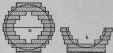
Fig. 204.
The method of constructing the core box for this or similar patterns, is shown at b, fig. 204.
Tees, elbows, and other bends and connections, when large, are built up in a similar way, thus making a lighter, and also more durable pattern.

Fig. 205.

Fig. 206.
For large cylinders, a much lighter and simpler method of constructing the pattern is shown in Fig. 206. For each half of the pattern the two end discs, and the middle semicircular disc are connected together by a strong center bar, which is fitted, glued and screwed into each, serving not only to strengthen the pattern, but also to hold the connecting dowel pins. When the two halves of the pattern are clamped together (with staples) it serves also as a secure means of centering in the lathe.

Fig. 207.

Fig. 208.
The staves forming the body of the cylinder are fitted and glued to each other and screwed, or nailed to the discs. After the cylinder has been turned, the core prints and flanges are built up and turned separately, and glued and screwed to the ends of the cylinder from the inside of the end discs.

SELF-CONTAINED AUTOMATIC ENGINE. The Brownell Company.
Fig. 207 illustrates still another and better method of building up the cylinder and core prints in one piece and completing the whole at a.single turning. The core prints, as shown, are staved up first.and then the staves to form the body of the pattern are fitted, glued and screwed, or nailed, over the ends of those which form the core prints. Should the body of the cylinder be long, one, two, or more middle semicircular discs must be used.
A similar construction for the core box is shown in Fig. 208, and is to be preferred to all others because if laid out and built to the exact size, the labor required to reduce the staves to a perfect semicircle of the required radius is very little.
Continue to:
My Books

