Globe Valve
Description
This section is from the book "Modern Shop Practice", by Howard Monroe Raymond. Also available from Amazon: Modern Shop Practice.
Globe Valve
The globe valve, shown in section in Fig. 218, is a good illustration of a pattern in which, while the outside may be very simple, the inside is intricate and requires considerable practice and skill to so contract the core boxes that the core can be withdrawn from them, and at the same time give uniform thickness and strength to all parts of the shell and to the internal partitions.
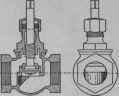
Fig. 218.
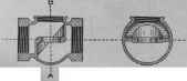
Fig. 219.
Fig. 219 is shown a sectional view of the body of the valve, 0 an illustration of the completed pattern, from that almost the entire work, with the exception ig the dowel pins, and forming the two hexagonal in the lathe. The construction is shown in the ition of the half-pattern. Fig. 221. The wood for must be of sufficient length to allow for gluing at r the insertion of iron staples. In turning, the 1st be taken to center exactly on the parting line of arefully shaped template, such as is shown at a, Fig. 221. used in turning. This template may be made of a thin wood, but for all purposes for which templates are in pattern making, and their use is necessarily very great, sheet zinc is the best material. It is soft, and easily cut and filed, and does not dull the cutting tools so much as other metals.

Fig. 220.

Fig. 221.
Before marking out the template, that the lines may be more readily seen, it should be cleaned with a piece of emery cloth and have a dark coating of the following solution. Dissolve an ounce of sulphate of copper in about four ounces of water and to this add one teaspoonful of nitric acid. Treat the surface of the zinc with this solution, rubbing on with a piece of waste. A thin coating of copper will thus be given to the zinc (also to steel or iron). When applied to finished surfaces they should be rubbed dry, as iron or steel will be rusted.
When the curves of the template will allow of sawing, the zinc template is easily shaped by placing a piece of zinc of the necessary size between two boards, and nailing them together. The required shape having been drawn on the upper board, the whole may be sawed to the form required on the band saw or scroll saw, but preferably on the latter, with a fine tooth narrow saw blade which will give a smoother edge to the zinc. If the boards are firm, the metal will offer no resistance whatever to the saw, nor will the saw be perceptibly dulled. For small curves, lay the zinc on a piece of hard board, and with a pair of sharp pointed dividers the zinc can be scratched half way through its thickness, then by turning it over and placing the dividers in the same center, the other side may be cut in the same way, or so nearly through that it will break off. This affords a truer and more uniform curve than can be obtained in any other way. The legs of the dividers must be stiff and firm so as to be entirely free from vibration. After cutting, the sharp edges of the zinc may be dressed with a fine double-cut file, or better with fine emery cloth or sand paper rolled over a wooden holder.
The lathe should always be stopped when testing the work with the template, and great care must be taken to make the two ends of the pattern symmetrical.
When the turning is nearly completed the template itself may be tested by reversing the ends. If not true it should be filed to the proper shape as shown by the drawing.
The branch e must bo turned in the same way as described for the main part of the pattern which is pared off, or planed off in a large pattern, to the exact size of the base of the branch, and when the pattern is large and heavy, one or two wood screws should be readily seen, allows the core to be easily removed when the box is opened. The lower part d, Fig. 224, of the core is made, in the box shown in Fig. 223. The part c has a square tenon which fits into the mortise in the part d. This mortise is made in the core by means of the print marked Y in Fig. 223, and as will be seen by Fig. 224, this core tenon and mortise will bring the two parts of the core into perfect alignment when they are pasted together.


Fig. 222.
In Fig. 225, we have an outside view of the completed core and in Fig. 226 a sectional view through the middle of the core, lengthwise; from which the necessity for the tenon and mortise connection will be readily understood, this being the only connection between the two parts of the core. In working out the core boxes it is well to use templates which can be formed and made from the drawings furnished. The templates will aid in getting the proper shapes, and leaving a uniform amount of metal in all parts of the case.

Fig. 227.

Fig. 228.
Figs. 222 and 223 illustrate the common wooden core box, but to insure uniformity, and because of the necessary wear and fragile character of wood for boxes of this kind, these core boxes should be made of metal. The wooden pattern for the metal core-box must then have an allowance for double shrinkage, and to to weight, the box is made in the form shown in Figs. and 288. Id this form all unnecessary metal is removed and connecting iron dowel pins are placed in lugs or thin outside lections as indicated.
Fig. 229.

Fig. 230.
Fig. 231.
Eg. 229 illustrates the pattern for the stuffing box and bonnet he valve, with core print tamed on each end, which, like the main pattern of the valve must be parted, or made in two halves. Two core boxes are necessary to make the core for this part of the valve. from Fig. 230 it will be seen that the core box for the lower end of the core can be turned out on the lathe by using a template of the required shape. For the upper part or stem, the half box shown in Fig. 231, is all that is necessary. By examining the two core boxes. Figs. 230 and 231. it will be seen that here again we have recourse to the tenon and socket form of construction for uniting the two parts of the core which are shown pasted together in the completed core, Fig. 232. The nut for the bonnet is shown in Fig. 233, and the pattern, which is hexagonal, should be so made as to form its own core, as indicated by the dotted lines in the drawing. Fig. 234 shows the pattern for the valve and also the pattern for the valve nut, each of which will form its own core, and Fig. 235 is an illustration of the pattern for the valve spindle.
Fig. 232.

Fig. 233.

Fig. 234.
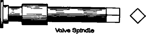
Fig. 235.
Continue to:
My Books

