Friction Clutches
Description
This section is from the book "Modern Shop Practice", by Howard Monroe Raymond. Also available from Amazon: Modern Shop Practice.
Friction Clutches
Notation
The following notation is used throughout the chapter on Friction Clutches:.
a =Angle between clutch face and axis of shaft (degrees)
H = Horse-power (33,000 ft.-lbs. per minute).
μ = Coefficient of friction (per cent).
N =Numberof revolutions per minute.
P = Force to hold clutch in gear to produce W (lbs.).
R =Mean radius of friction surface (inches).
T =Twlsting moment about shaft axis (inch-lbs.).
V = Force normal to clutch face (lbs.).
W=Load at mean radius of friction surface (lbs.).
Analysis
The friction clutch is a device for connecting at will two separate pieces of shaft, transmitting an amount of power between them to the capacity of the clutch. The connection is usually accomplished while the driving shaft is under full speed, the slipping between the surfaces which occurs during the throwing-in of the clutch, permitting the driven shaft to pick up the speed of the other gradually, without appreciable shock. The disconnection is made in the same manner, the amount of slipping which occurs depending on the suddenness with which the clutch is thrown out.
The force of friction is the sole driving element, hence the problem is to secure as large a force of friction as possible. But friction cannot be secured without a heavy normal pressure between surfaces having a high coefficient of friction between them. The many varieties of friction clutches which are on the market or designed for some special purpose, are all devices for accomplishing one and the same effect, viz., the production of a heavy normal force or pressure between surfaces at such a radius from the driven axis, that the product of the force of friction thereby created and the radius shall equal the desired twisting moment about that axis.
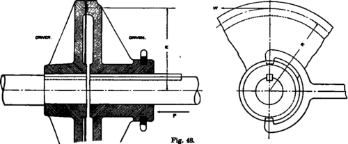
Three typical methods of accomplishing this are shown in Figs. 48, 49, and 50. None of these drawings is worked out in operative detail.
They are merely illustrations of principle, and are drawn in the simplest form for that purpose.
In Fig. 48 the normal eated in the simplest possible way, an absolutely direct push being exerted between the discs, due to the thrust P of the clutch fork


In Fig. 49 advantage is taken of the wedge action of the in. clined faces, the result being that it takes less thrust P to produce the required normal pressure at the radius It.
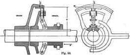
In Fig. 00 the inclination of the faces is carried so far that the angle a of Fig. 49 has become zero; and by the toggle-joint action of the link pivoted to the clutch collar, the normal force produced may be very great for a slight thrust P. By careful adjustment of the length of the link SO that the jaw takes hold of the clutch surface, when the link stands nearly vertical, a very easy operating device is secured, and the thrust P is made a mini-nmm.
Theory
Referring to Fig. 48 in order to calculate the twisting moment, we must remember that the force of friction between two surfaces is equal to the normal pressure times the coefficient of friction. This, in the form of an equation, using the symbols of the figure, is :
W = μ p. (88)
Hence we may consider that we have a force of magnitude μP acting at the mean radios R of the clutch surface. The twisting moment will then be :
T = WR = μPR. (89)
Referring to equation 54, which gives twisting moment in terms of horse-power, and putting the two expressions equal to each other, we have :
T = 63,025H / N = μPR;
H = μNPR / 63,025 (90)
This expression gives at once the horse-power that the clutch will transmit with a given end thrust P.
In Fig. 49 the equilibrium of the forces is shown in the little sketch at the left of the figure. The clutch faces are supposed to be in gear, and the extra force necessary to slide the two together is not considered, as it is of small importance. The static equations then are:
P = 2 V / 2 sin a; or, V = P cosec a. (91)
W = μV = μP cosec a. (92)
T=WR = μPR cosec a. (93)
T = 63,025H / N = μPR cosec a; or, H = μNPR cosec a / 63,025. (94)
In Fig. 50, P would of course be variable, depending on the inclination of the little link. The amount of horse-power which this clutch would transmit would be the same as in the case of the device illustrated in Fig. 49, for an equal normal force V produced.
The further theoretical design of such clutches should be in accordance with the same principles as for arms and webs of pulleys, gears, must be liberal in order to prevent tipping on the shaft as a result of uneven wear. The end thrust is apt to be considerable; and extra side stiffness must be provided, as well as a rim that will not spring under the radial pressure.
Practical Modification
It is desirable to make the most complicated part of a friction clutch the driven part, for then the mechanism requiring the closest attention and adjustment may be brought to and kept at rest when no transmission of power is desired.
Simplicity is an important practical requirement in clutches. The wearing surfaces are subjected to severe usage; and it is essential that they be made not only strong in the first place, but also capable of being readily replaced when worn out, as they are sure to be after some service.
The form of clutch shown in Fig. 50 is the most efficient form of the three shown, although its commercial design is considerably different from that indicated. Usually the jaws grip both sides of the rim, pinching it between them. This relieves the clutch rim of the radial unbalanced thrust.
Adjusting screws must be provided for taking up the wear, and lock nuts for maintaining their position.
Theoretically, the rubbing surfaces should be of those materials whose coefficient of friction is the highest; but the practical question of wear comes in, and hence we usually find both surfaces of metal, cast iron being most common. For metal on metal the coefficient of friction μ cannot be safely assumed at more than 15 per cent, because the surfaces are sure to get oily.
A leather facing on one of the surfaces gives good results as to coefficient of friction, μ having a value, even for oily leather, of 20 per cent. Much slipping, however, is apt to burn the leather; and this is most likely to occur at high speeds.
Wood on cast iron gives a little higher coefficient of friction for an oily surface than metal on metal. Wood blocks can be so set into the face of the jaws as to be readily replaced when worn, and in such case make an excellent facing.
The angle a of a cone friction clutch of the type shown in Fig. 49, may evidently be made so small that the two parts will wedge together tightly with a very slight pressure P; or it may be so large as to have little wedging action, and approach the condition illustrated in Fig. 48. Between these limits there is a practical value which neither gives a wedging action so great as to make the surfaces difficult to pull apart, nor, on the other hand, requires an objectionable end thrust along the shaft in order to make the clutch drive properly.

Fig. 51.

SINGLE PUNCHING OR SHEARING MACHINE. Capacity 4½ inch hole in 1-iueh plate.
For a = about 15°, the surfaces will free themselves when P is relieved. " a = " 12°, " " require slight pull to be freed. " a = " 10°, " " cannot be freed by direct pull of the hand, but require some leverage to produce the necessary force P.
Problems On Friction Clutches
1. With what force must we hold a friction clutch in to transmit 30 horse-power at 200 revolutions per minute, assuming working radius of clutch to be 12 inches; coefficient of friction 15 per cent; angle a = 10° ?
2. How much horse-power could be transmitted, other conditions remaining the same, if the working radius were increased to 18 inches ?
3. What force would be necessary in problem 1, if the angle a were 15°, other conditions remaining the same ?
Continue to:
My Books

