Gear Wheel Patterns. Part 3
Description
This section is from the book "Modern Shop Practice", by Howard Monroe Raymond. Also available from Amazon: Modern Shop Practice.
Gear Wheel Patterns. Part 3
Small gears, or pinions as they are called, are usually made with a solid web instead of arms, and are glued up in solid blocks of end wood, the grain of the entire block running parallel with the face of the teeth. Such an end wood pinion is shown in Fig. 243, It is turned and the gear laid out and cut in the same way as described for the larger wheels, except that the teeth are not glued on but cut out in the solid disc. In the construction shown in Fig. 241, the teeth, not being screwed on, must be nailed with brads, after being shaped and finished, from the face of each tooth into the rim.

Fig. 243.
Patterns for Bevel Gears are built up as illustrated at a, Fig. 244, the wooden face-plate, or chuck, being provided with ten or more radial blocks as shown and described in Fig, 168. The advantage of the blocks is that they keep the first layer of segments out from the face-plate and give easier access to the back edge or angle of the rim while being turned.
The segments are usually made to overlap as shown, which is not only a saving of wood but also saves the time which would be required to turn the angular rim from a square construction. When a sufficient number of courses have been built up, the face and two edges are turned to the required angles, as indicated by the dotted lines in a, Fig. 244. The rib c which will finally be a continuation of the arms, is also turned to shape and to the thickness of the ends of the arms. The rim will then present the appearance shown at b, Fig. 244, except the arms which are here shown in place.
The rim is next cut from the blocks, and an angular groove turned in the face of the chuck which will fit and center the finished edge of the rim on the faceplate. In this position the inside of the rim is turned and finished as shown in Fig. 245, The rim is retained on the chuck by four or six cleats, d, Fig. 245, the cleats fitting over the rib c, Fig. 244, and preventing the rim from moving and changing its position on the chuck.
It is not necessary here to describe the method used in finding the required angles for the face and edges of the rim, but as in the case of spur-gear teeth, the student should refer to Mechanical Drawing. The arms, partly shown in Fig. 246, in place in Fig. 244, are next fitted and fastened to the rim. It is well to glue a small disc on each side of the web of the arms as shown in Fig, 246, which not only strengthens the arms, but serves as a fillet around the hub of the wheel.

Fig. 244.
Fig. 245.
The blocks for the teeth are next fitted in place, either as illustrated in Fig, 247, or in the form of alternate blocks and strips as was shown for the spur gear, Fig. 237. After all the blocks are in place, the wheel must be put in the lathe and turned to the sizes and angles required for laying out the teeth. A sharp line must be drawn on the face of the blocks, while in the lathe, to serve as a guide for the dividers while spacing the teeth.
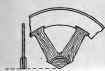
Fig. 246.

Fig. 248.
To obtain the center lines for the tooth faces after spacing on the blocks, it will be readily seen that the ordinary try square cannot be used as in the case of the spur gears. A temporary square must be made for this purpose as follows:
Take a piece of hard wood, about 6 inches long and 3½ inches wide and ½ inch in thickness. Dress the two edges perfectly parallel and from the upper edge a, Fig. 248, with a try square and a sharp pointed knife, draw the line c, equally distant from each end of A, and at right angles to the edge a. Lay the edge b of A, against another board B, of the same thickness, and continue the line c on this board as shown by the dotted line. With the dividers set to a radius equal to the longest radius of the outside ends of the tooth blocks, from the extended line c on the board B, describe the arc, x y on A. Cut the edge b, to this arc and see that it fits perfectly the outer rim of the tooth block. Next make a thin blade of hard wood and screw to the head A, using the greatest care to have one edge of the blade coincide exactly with the line c. After screwing the blade to the head, its accuracy may be tested by placing a try square against the edge a. The result will be as shown in Fig. 249, in which the edge c is radial to the arc to y. This edge will describe the center lines of the teeth radially as required.
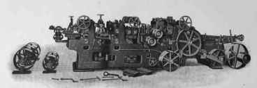
FIXED KNIFE PLANER FOR HARDWOOD FLOORING. J. A. Fay and Egan Co.

Fig. 347.
This temporary square can be used up to a certain limit, on wheels of larger diameter than that to which it has been fitted, but cannot be used for smaller wheels. For larger gears the position will be as shown in Fig. 250, which will give the correct perat x and y are carefully made. By using ires will be needed for a great number of wheels. In Fig. 247 the hub H and the ribs of the arms R R. are often made loose so as to lift with the cope, which is of great advantage in moulding. When the teeth are large, they must be screwed on from the inside of the rim. If small, they should bo braded from the outside, or face of the tooth, into the rim after the teeth have been shaped and finished. Two templates will be necessary for laying out the ends of the teeth, the outer ends being larger than the inner. These templates are made as described for spur gears, and have the outer end bent to fit over the angles of the rim.

Fig. 249.

Fig. 250.
Continue to:
My Books

