Brick. Part 5
Description
This section is from the book "The Engineer's And Mechanic's Encyclopaedia", by Luke Hebert. Also available from Amazon: Engineer's And Mechanic's Encyclopaedia.
Brick. Part 5
The axes of the polygonal drums revolve in plummer-blocks, supported upon a strong frame s; but as the polygonal drums revolve in close contact, the plummer-blocks are free to slide in grooves in the frame, and the wheels are kept in contact by the action of strong helical springs t, which press against the plummer-blocks, the other end of the springs abutting against a regulating screw. In the middle of, and underneath, the horizontal frame s, is fixed a knife u (supported in its place by a spiral spring), which separates the whole or a portion of the superfluous materials from each mould, as the latter passes over the edge of the former. As some redundancy of material may still be left after the operation of the knife u, the exposed surface of the moulds in motion undergoes a similar treatment from two other knives v v, fixed to the foundation plate w of the machine. A trough or cistern k k containing water, is placed under each of the drums, the lowest sides of which come in contact with a cylinder y, covered with strong coarse cloth or other suitable absorbent substance, which, as it revolves, takes up the water and delivers it to the moulds, as before mentioned.
These cylinders are mounted on elastic bearings, and derive their motion from pinions on their axes, actuated by the toothed wheels on the drums. In the centre of the foundation plate there is a cavity, or pit, for the reception of the superfluous clay or other materials, which are removed at pleasure. The pug mill has a door in it, for the convenience of cleaning it out when requisite; and the whole of the upper part of the machine is supported by three columns z z z. The polygonal drums are driven by a set of wheels lying at the back of Fig. 1, and therefore in that figure shown by dotted circles. No. 1 is a band wheel, which drives the rest; it is affixed to one of the columns, and has a pinion 2 attached to it, that drives a larger wheel 3, running loose on the shaft of one of the drums. This last propels another large wheel 4, fixed on the shaft of the other drum, gearing into each other; they are driven round together, but in opposite directions. Since our drawings of this machine were taken, we understand that the patentee has made some improvements in the arrangement of his driving wheel, which renders the action of the parts very steady and uniform.
In case of negligence on the part of the boys, or other attendants of the machine, in not removing the bricks or tiles after the moulds containing them have passed the centre of the eccentric wheel, they fall back into their former position, and pass round to the place of delivery, as before, without any damage whatever being done to the machine. Having explained the general arrangement and operation of the machine, there remains to be described the construction of the detached moulds. Fig.3 represents a side view, and Fig. 4 an end view, of one of these. The ends of the mould 18,18, are made of wood, plated at the edges with iron, and fastened on by screws, as seen in Fig. 3. The bottom 19 is also of wood, but cased in a strong frame of cast iron, and at its two extremities are jointed to the ends 18, 18, so as to open only a little way, for allowing the brick to separate freely from it upon inverting the mould. This effect is facilitated by lining the interior of the mould with cloth, which, although constantly in a wet state, admits air to pass through its interstices when the clay is forced into the mould, so that when the brick is afterwards forced out, the moisture of the cloth, and the spring of the confined air, delivers the brick uniformly clean, without the adhesion of any clay.
It will be observed that the two ends 18 of the mould have each a cavity; these cavities receive the fingers of the workman when he takes hold of the mould, which he afterwards inverts, drawing back the ends 18 at the instant, and pressing with his thumb upon the screw heads 21 21, the other ends of which are attached to a plate 22 underneath the cloth lining of the bottom, as shown by dots, causing the brick to be immediately disengaged. The two sides of the brick not included in the detached mould are formed by the partition between the mould boxes and the hollow sectors. The forms and dimensions of the detached moulds are varied according to the nature of the articles to be produced therefrom. For adapting the machine to make tiles, or other articles of a greater length than a brick, two movable blocks, which usually lie inside the hopper, to contract its lower dimensions, are taken out. In the making of drain tiles, and other articles having cavities within them, jointed horses or cores are employed; the plastic matter is forced around them by the action of the machine in the same manner as in forming a brick, and the subsequent operations are also the same, except that in the removal or delivery of such tiles from their moulds, suitable adaptations are made to prevent their being pressed or even touched by the hand.
The annexed Fig. 5 exhibits another arrangement employed by Mr. Nash for making flat tiles, flooring tiles, etc. of any required breadth and thickness. This cut only represents the lower part of the machine, the upper being the same as in the previously described apparatus. To the bottom of the pug mill is fixed a funnel-shaped hopper 23, the materials in which, after being forced through a mouth 24, formed of the required shape, are received upon boards 25, and when cut to the proper length, are removed to sheds for drying. In order to equalize the surface of the clay after it has come out of the hopper, a roller 26 turning in bearings on a curved arm, which is fixed to a hinge joint, gives to the material any pressure that may be required, by loading it accordingly. The dotted lines 27, 27 in the same figure, exhibit another funnel-shaped hopper, for the purpose of making pipes or tubes, by means of a centre core 28, between which and the cylindrical continuation of the hopper, the material is forced by the action of the pug mill, and produces a tube, which, after having made a certain length of, is cut off, the tube being turned round, to render the inside smooth previously to its being removed.
The patentee states that this machine may be used with either one or two horse power; that when used with one horse power, the product is about 700 per hour, or 8000 per day; to do which requires the services of two men and eight boys, occasioning an expense not exceeding two shillings and sixpence per 1000. With two horse power employed, the production is double, or 16,000 per day; but the quality of the bricks, which the editor has seen, is equal to those which are usually finished by grinding the surfaces by hand. The saving of labour in the production is about two shillings per 1000; but the quality rendering them worth five shillings per 1000 more in the market, the advantage of making by the machine, where good bricks are required, is equal to seven shillings per 1000.
Fig .1.
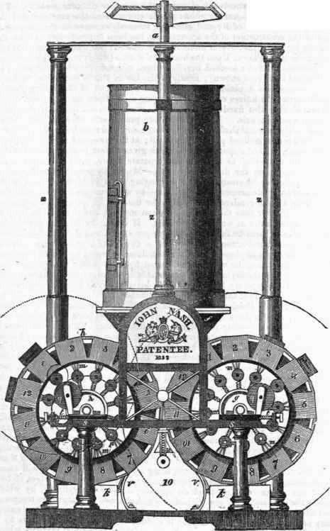
Fig. 2.


Fig. 4.
Fig. 3.

Fig. 5.

Continue to:
My Books

