238. Drawing A Pattern From The Mould
Description
This section is from the book "An Elementary Outline Of Mechanical Processes", by G. W. Danforth. Also available from Amazon: An elementary outline of mechanical processes.
238. Drawing A Pattern From The Mould
After the sand is packed about the pattern in a mould, the pattern must be withdrawn before the mould can be filled with metal. In determining how a pattern shall be built, the first consideration is to decide how it shall rest in the mould with relation to the joints between the parts of the mould, so that it may be withdrawn without tearing the sand. It is usual to give a pattern a slight taper to facilitate its withdrawal.
This taper or "draft" is all that is necessary for the ready withdrawal of small and simple patterns, but the majority of patterns are of such shapes that they must be made in two or more parts, easily separable, to get them out of the mould. These parts are held together by dowel pins. A pattern is usually divided along its plane of symmetry into two parts, and is so moulded that this division coincides with the parting of the mould. A mould is also usually made in two parts, the upper of which is called the cope and the lower is called the drag or nowell. When the upper part of the mould is lifted away from the lower part, the upper part of the pattern is lifted with it. Each part of the pattern can then be lifted from the sand after a light rapping.
If either part of the pattern has any projection which would tear the sand in withdrawing, it must be dowelled in place in such a manner that it will be left behind when the part to which it is attached is withdrawn, or else the mould must be so built that a section of it may be taken away as a " drawback" before that part of the pattern is lifted out.
Figs. 108 and 109 show examples of simple patterns suitably made for withdrawing from the moulds.
Fig. 108 shows two views of a gland G to be cast hollow. The bolt holes b in the flange and the taper at the end d are cut in the machine shop after the casting is made. This gland is cast from the pattern H, placed horizontally in the mould. The halves of the pattern are separated in the view to show the line of parting. The bolt holes are reinforced by small raised pieces h, cast with the flange. If these projections were made fast on the pattern they would tear the sand of the mould when each half of the pattern was lifted out in the directions of the arrows, hence they are held on the pattern flange by small wires k which are withdrawn when enough sand has been rammed against the flange to hold the projections in place. The pattern may then be withdrawn from the mould, leaving the projections behind, and these are drawn out horizontally into that part of the mould space which was occupied by the flange.

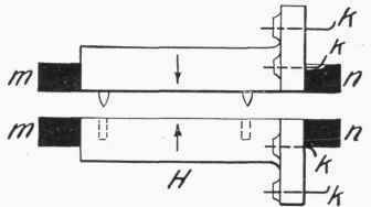
Fig. 108. - Metal Casting and its Pattern.


Fig. 109. - A Casting and its Patterns.
In Fig. 109 the moulds B and C, of the same casting A, show two methods of constructing a pattern for ready withdrawal from the sand. The mould B is the simpler. In this mould, the cope is lifted, the parts marked 1 are lifted out together, and the parts marked 2 and 3 are then removed by first drawing them horizontally into the space left by the lower part of 1.
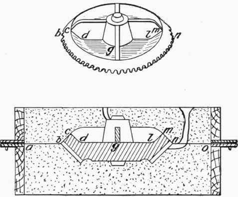
Fig. 110. - Pattern and Mould of Gear Wheel.
In the mould C, parts 4 and 5 are merely dowelled together. The cope is lifted, part 4 is lifted, and the cheek is then lifted, leaving part 5 on the parting between the cheek and the drag. In a mould of three parts, the middle part is called the cheek.
The pattern of the bevel wheel shown in Fig. 110 is made in two parts. The hub and the spokes are made as one part. The mould of the wheel is parted along the line ah c d g l m n o, so that the hub and spokes will lift with the cope. 15
Continue to:
My Books

