266. Building A Loam Mould
Description
This section is from the book "An Elementary Outline Of Mechanical Processes", by G. W. Danforth. Also available from Amazon: An elementary outline of mechanical processes.
266. Building A Loam Mould
Each of the detachable parts of a loam mould is so built on its own plate that it can be handled separately from the other parts.
The mould is begun by leveling the heavy foundation plate B (Fig. 129) on firm supports, and supporting the spindle 8 vertically in its bearings in which it is free to turn. Sweep No. 1, with edges iron bound to prevent wear from the rough loam, is then bolted to the strap A. The foundation brickwork C is built up with this sweep as a guide, and about half an inch of loam is swept evenly over the top of the brickwork by revolving the sweep about the spindle. This loam facing, shown in Fig. 130, is allowed to dry and the joint JJ is well oiled.
The next part of the mould, the main body (marked GG in Figs. 127 and 131), is swept up on the lifting ring D by using sweeps 2 and 3. The steps of this work are shown in Figs. 130 and 131. The lifting ring is bedded in a layer of wet loam spread over the joint J J. This loam sticks to the ring when dry and is. lifted with it. Sweep No. 2 merely sweeps the temporary brickwork FF, which is loam coated to serve as a pattern against which the lower part of the main body is built. The revolving of the sweeps as the bricks are placed serves as a guide in placing them, and after the brickwork is done, the loam coating is plastered on by hand and swept to shape on the brick surface to form the surface of the mould, which is later made very smooth.
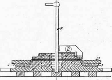
Fig. 130. - Sweeping up Dummy Flange.
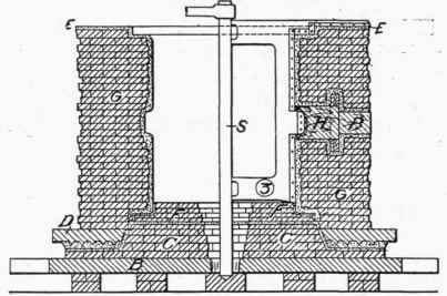
Fig. 131. - Sweeping up Main Wall.
Any part of the casting, as the nozzle of the cylinder in Fig. 128, which projects beyond the surface of revolution, is moulded by bedding suitable wooden patterns of these parts in the brickwork. The pattern H, with its core print P (Fig. 131) and its detachable flange, is surrounded by a loam coating as it is built in the wall of the mould. These patterns are removed after the mould is lifted apart.
When sweep No. 3 has completed its work, as shown in Fig. 131, the main part is lifted away on its lifting ring D, the temporary work FF is torn away, and the main core K, for making the cylinder hollow, is swept up as shown in Fig. 132. L is a small core print for the nozzle core, and R is a flat bar of cast iron imbedded in the core. The bar is removed just after the cylinder is cast, by digging down to its end and attaching the crane thereto. This removal allows the casting to crush the core sufficiently in contracting to avoid cracking.
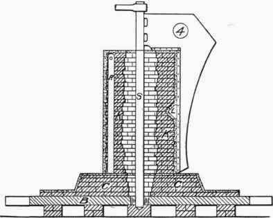
Pig. 132. - Sweeping up Main Core.
The assembled mould in Fig. 127 shows the top plate TT placed over the oiled joint EE. Loam has been swept on the under side of this plate and after the parts of the mould are assembled and bound, the riser and pouring basins are shaped of green sand held in place by the sheet-iron ring V and the heavy tube Q. The four-armed cross M, resting on distance pieces Q and SS, is bound to the foundation plate B as shown.
The parts of the mould are dried after they are swept up and lifted apart. This is done in a large brick oven and requires about 60 hours. Before finally assembling, the mould surfaces are painted with a liquid mould facing and carefully slicked by hand slickers.
Continue to:
My Books

