Caissons. Part 12
Description
This section is from the book "Notes On Construction In Mild Steel", by Henry Fidler. Also available from Amazon: Notes On Construction In Mild Steel.
Caissons. Part 12
The hydraulic cylinders themselves are of an ordinary type, of cast steel, lined with gun metal, the net internal diameter of the cylinder being 13 inches, and the diameter of the upper portion of the piston rod 4 inches, the lower rod being 5 inches diameter. The upper end of the rod is provided with lock nuts, capable of adjustment so as to limit the amount by which the caisson keels could be lifted off their ways, a surplus amount of stroke of ram being provided to meet any possible settlement of the roller path.
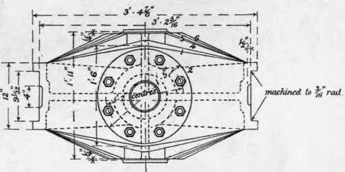
Fig. 407. Scale ¾ inch = 1 foot.

Fig. 408. Scale ¾ inch = 1 foot.
Numerous tests of the cast steel used in the manufacture of the rollers and hydraulic ram cylinders will be found on p. 71 in the table of tensile and bending tests on cast steel bars.
A mud scraper is provided at both ends of the caisson on both granite keelways, placed athwart the ways. This consists of a steel casting arranged, as shown in Fig. 409, to receive a 2.inch thick slab of vulcanised india-rubber.
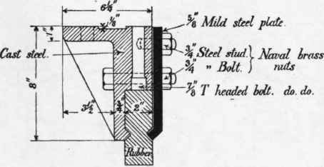
Fig. 409. Scale 1½ inch = 1 foot.
Handrailing to sliding caissons is usually arranged to act automatically, by means of lever arrangements of bars and counterbalance weights, so that upon the caisson being set in motion to enter the camber, the whole of the handrailing commences to fall into troughs prepared for the purpose, and remains stowed away until the end of the return journey, when it is caused to resume its vertical position by the power of the hauling engines.
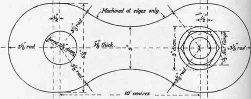
Fig. 410. Scale 3 inches = 1 foot.
The hauling chains of sliding caissons are sometimes of ordinary link or stud-link chain, wound on barrels and supported by rollers at intervals. A superior mechanical arrangement, though perhaps more expensive, is found in the use of the type of chain shown in Figs. 410 and 411, Fig. 410 being an elevation of one link, Fig. 411 a detail of pin connection, and Fig. 412 a detail of the screw coupling for the purpose of the adjustment of length, and for the taking up of preliminary stretch in the chain.

Fig. 411. Scale 3 inches = 1 foot.
Chains of this type have been used for sliding caissons having a total mass to be hauled of 1100 tons, including ballast. Two chains are employed, one on each side, each chain consisting of two links, each link having a section of 3" X ⅞" at the waist of the link. The total collective sectional area of the two chains available for pull is therefore 10.5 square inches, and the chains are designed for a maximum working hauling power of 70 tons on the two chains.

Fig. 412. Scale ¾ inch = 1 foot.
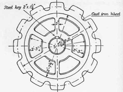
Fig. 413. Scale ¾ inch = 1 foot.
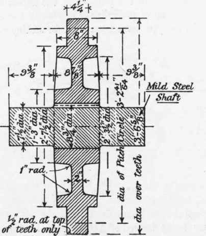
Fig. 414. Scale ¾ inch = 1 foot.
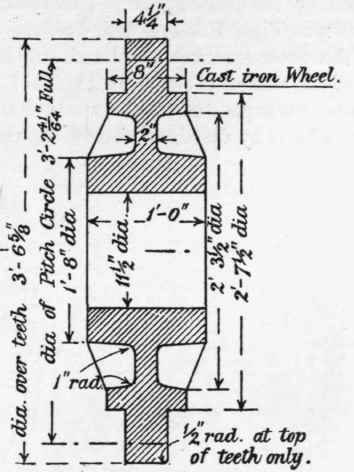
Fig. 415. Scale ¾ inch = 1 foot.

Fig. 416. Scale ¾ inch = 1 foot.
The chains are endless, passing over two sprocket wheels, one at the forward end of the caisson camber and one at the engine end, actuated by the engine gear. The sprocket wheels of cast iron are shown in Figs. 413, 414, 415, 416, and the massive casting supporting the outer sprocket wheel and attached to the masonry of the side of the camber is shown in Figs. 417, 418.
The chains are supported for the whole of their length between the sprocket wheels by cast-iron girders, shown in Figs. 419, 420, supported by cast-iron brackets, as shown in Fig. 421, attached to the caisson camber walls, the upper surface of the girder upon which the chains travel being machined.

Fig. 417. Scale ½ inch = 1 foot.
The chain links, pins, and nuts are of mild steel. Tests of the material employed will be found in the table of the strength of steel for special purposes, p. 46. The edges only of the links are machined, the flat sides being left with a flat surface as they come from the rolls. The holes for pins are drilled carefully to gauge, and the pins made a close fit in the holes. The nuts are drop-forged and machined on meeting face only, made a tight fit on the screwed portion of the pin but without gripping the links, which are free to turn when revolving round with the sprocket wheels.

Fig. 418. Scale ½ inch = 1 foot.
Care is taken in shaping the teeth of the wheels to avoid any possibility of the links riding up.
The whole of the chains are each tested to a proof load of 40 tons in separate lengths of from 110 to 118 feet, the tests being made by an hydraulic ram and the pull ascertained by a dynamometer.
Upon the application of the first pull on the chain, which involved tensile stresses gradually increasing from zero to 7.6 tons per square inch on the section of the waist of the link, a residuary permanent set was always found upon the removal of the load, amounting on the average to 0 0011 of the length of chain tested (about 110 to 118 feet).

Fig. 419. Scale ½ inch = 1 foot.

Fig. 420. Scale ½ inch = 1 foot.
Continue to:
My Books

