


Cutters For Boiler-Plate And Similar Work
Description
This section is from the book "Wrinkles And Recipes, Compiled From The Scientific American", by Park Benjamin. Also available from Amazon: Wrinkles and Recipes, Compiled From The Scientific American.
Cutters For Boiler-Plate And Similar Work
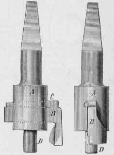
Cutters are steel bits, usually held in either a Mock or bar, being fitted and keyed to the same; by this means, cutters of various shapes and sizes may be made to fit one stock or bar, thus obviating the necessity of having a multiplicity of these tools. Of cutter-stocks, which are usually employed to cut out holes of comparatively large diameter, as in the case of tube-plates for boilers, there are two kinds, the simplest and easiest to be made being that shown below.
Cutters
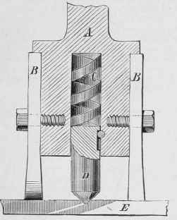
A is the stock, through which runs a slot or key way into which the cutter, B, (its, being locked by the key, C. D is a pin to steady the tool while it is in operation, Holes of the size of the pin, 1', are first drilled in the work, into which the pin fits. To obviate the necessity of drilling these holes, some modern drill stocks have, in place of the pin, D, a conical ended pin which acts as a centre, and which fits into a centre punch mark made in the centre of the hole to be cut in the work Most of these devices are- patented, and the principle upon which they act will be understood from the second engraving, A being the stock to which the cutters, B B, are bolted with one or more screws. C is a spiral spring working in a hole in the stock to receive it. Into the outer end of this hole fits, at a working fit, the centre, D, which is prevented from being forced out (from the pressure of the spring, C) by the pin working in the recess, as shown. E is the plate to be cut out, from which it will be observed that the centre, D, is forced into the centre-punch mark in the plate by the spring, C, and thus serves as a guide to steady the cutters and cause them to revolve in a true circle, so that the necessity of first drilling a hole, as required in the employment of the form of stock shown in the first figure, is obviated.
Cutters
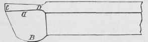
Cutting Square Threads, Tools for.-For cutting square threads, the tool here represented is used. The point at C is made thicker than the width at D, so as to give the sides clearance from the sides of the thread. At B it is made thinner, to give the tool clearance, and deeper to compensate in some measure for the lack of substance in the thickness. The top face may, for wrought-iron or steel, be ground hollow, C being the highest point, to make it cut cleaner; while, when held far out from the tool-post for use on brass-work, the face, C D, may be ground at an incline, of which C is the lowest point, which will prevent the tool from springing into the work.
Fig.14.
Tool For Cutting Square Threads
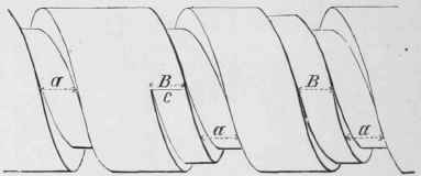
If the pitch of the screw to be cut is very coarse, a tool nearly one half of the width of the space between one thread and the next should be employed, so as to avoid the spring which a tool of the full width would undergo. After taking several cuts, the tool must be moved laterally to the amount of its width, and cuts taken off as before until the tool has cut somewhat deeper than it did before being moved, when it must be placed back again into its first position, and the process repeated until the required depth of thread is attained.
Screw During Cutting
The above figure represents a thread or screw during the above described process of cutting, a a a is the groove or space taken out by the cuts before the tool was moved; B B represents the first cut taken after it was moved; c is the point to which the cut, B, is supposed (for the purpose of this illustration) to have traveled.
The tool used having been a little less than one half the proper width of the space of the thread, it becomes evident that the thread will be left with rather more than its proper thickness, which is done to allow finishing-cuts to be taken upon its sides, for which purpose the knife-tool already described is brought into requisition, care being taken that it is placed true, so as to cut both sides of the thread of an equal angle to the centre-line of the screw.
Adjustable dies, that is. those which take more than one cut to make a full thread, should never be used in case- where a solid die will answer the purpose, because adjustable dies take every cut at a different angle to the centre line of the bolt, as explained by the following engravings.
The firs t represents an ordinary screw. It is evident that the pitch from a to B is the same as from C to D, the one being the top, the other the bottom, of the thread. It is also evident that a piece of cord wound once around the top of the thread will be longer than one wound once around the bottom of the thread, and yet, in passing once around the thread, the latter advanced as much forward as the former, that is, to the amount of the pitch of the thread. To illustrate this fact, let a b, in the following diagram, represent the centre-line of the bolt lengthwise, and c d a line at right angles to it; then let from the point e to the point f represent the circumference of the top of the thread, and from e to g the circumference of the bottom of the thread, the lines h h representing their respective pitches; and we have the line k as representing the angle of the top of the thread to the centre-line, a b, of the bolt, and the line l as representing the angle of the bottom of the thread to the centre-line, a b, of the bolt, from which it becomes apparent that the top and the bottom of the thread are at different angles to the centre-line of the bolt. The tops of the teeth of adjustable dies are themselves at the greatest angle, while they commence to cut the thread on the bolt at its largest diameter, where it possesses the least angle, so that the dies cut a wrong angle at first, and gradually approach the correct angle as they cut the depth of the thread. From what has been already said, it will be perceived that the angle of thread cut by the first cuts taken by adjustable dies, is neither that of the teeth of the dies nor that required by the bolt, so that the dies can not cut clean because the teeth do not fit the grooves they cut, and drag in consequence.
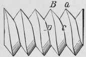
Ordinary Screw
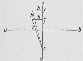
Dies for use in hand-stocks are cut from hubs of a larger diameter than the size of bolt the dies are intended to cut: this being done to cause the dies to cut at the cutting edges of the teeth which are at or near the centre of each die, so that the threads on each side of each die act as guides to steady the dies and prevent them from wabbling, as they otherwise would do; the result of this is that the angle of the thread in the dies is not the correct angle for the thread of the bolt, even when the dies are the closest together, and hence taking the finishing-cuts on the thread, although the dies are nearer the correct angle when in that position than in any other. A very little practice at cutting threads with stocks and dies will demonstrate that the tops of the threads on a bolt cut by them are larger than was the diameter of the bolt before the thread was commenced to be cut, which arises from the pressure placed on the sides of the thread of the bolt by the sides of the thread on the dies, in consequence of the difference in their angles; which pressure compresses the sides of the bolt-thread (the metal being softer than that of the dies), and causes a corresponding increase in its diameter. It is in consequence of the variation of angle in adjustable dies that a square thread can not be cut by them, and that they do not cut a good V-thread.
In the case of a solid die, the teeth or threads are cut by a hub the correct size, and they therefore stand at the proper angle; furthermore, each diameter in the depth of the teeth of the die cuts the corresponding diameter on the bolt, so that there is no strain upon the sides of the thread save that due to the force necessary to cut the metal of the bolt-thread.
Continue to:


My Books

