Syruping Bottling Apparatus
Description
This section is from the book "A Treatise On Beverages or The Complete Practical Bottler", by Charles Herman Sulz. Also available from Amazon: A Treatise On Beverages.
Syruping Bottling Apparatus
An important and indispensable contrivance calculated to facilitate the process of bottling carbonated beverages is the syrup gauge. This is a device for enabling the syrup to be rapidly and accurately measured and delivered into the bottle. It may either be attached to the bottling-machine or entirely separate from it.
Figs. 236, 237, 238 and 239 represent the syrup-gauges and pumps generally used in. the United States, and are attached directly to the bottling machine. Their capacity is from 3/4 of an ounce to 4 ounces of syrup per stroke, and the desired quantity is regulated by means of a movable pin or screw which guides the pumping strokes. By repeating strokes, any desired quantity of syrup may be gauged in one bottle. All these syrup gauges or pumps are made with close-fitting hard rubber plungers, which fill the entire cylinder - that is to say, they admit and discharge the syrup from the same end of the piston. It is necessary to have the syrup cans or tanks elevated in order to deliver the syrup to the syrup gauges. A gauge with suction pump will draft the syrup whether elevated or not. The syrup gauges and pumps are made of brass and ought to be carefully and frequently tin or silver lined inside, as the acidified syrups which are compelled to pass through all parts of it would soon affect the metallic body and get tainted with metallic impurities itself, and consequently contaminate the beverages. We have seen syrup gauges entirely covered with verdigris on the inside, and this is another point where the carbonator should exercise the closest scrutiny and cleanliness. The gauge must be frequently cleansed, and whenever the lining is worn out at once re-lined.
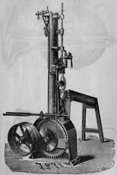
Fig. 231. - English Power Filling and Corking Apparatus.
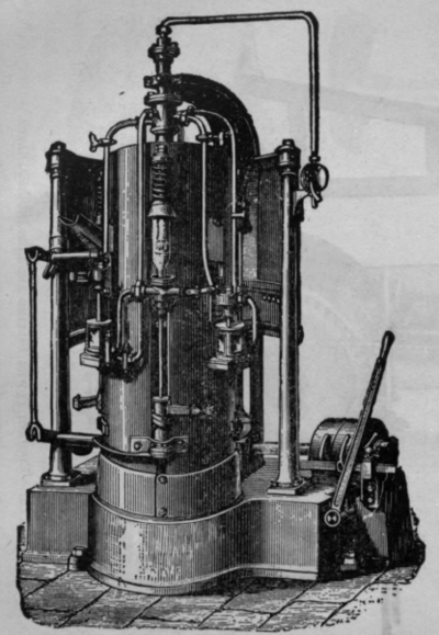
Fig. 232. - English Automatic SyRupinG and Filling Machine.
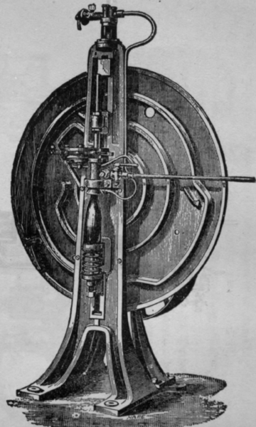
Fig. 233. - English Steam-Bottle Corking Machine.
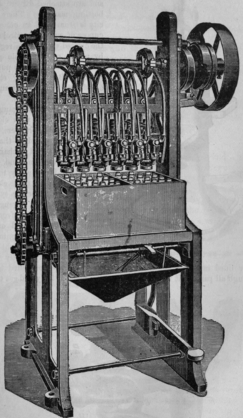
Fig. 234. - English Rapid Power Bottling Machine.
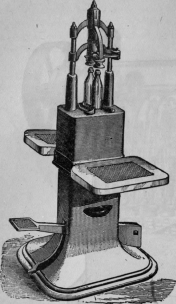
Fig. 235. - Bottling and Sealing Machine.
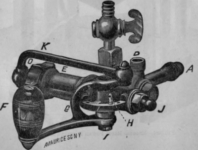
Fig. 236. - Matthews' Plunger Syrup Gauge.
The syrup can is connected with the gauge by means of a flexible rubber bose with the inlet C of gauge as shown in Fig. 236. The other inlet B is connected with the supply pipe for the plain carbonade, and A is the outlet for both the syrup and the beverage. F is the handle for operating the solid plunger; K is the connecting rod; T is a guide for the crank which operates the solid plunger, and H is a movable pin for regulating the stroke of the plunger, and thus gauging the quantity of syrup to be delivered to the bottle. In attaching the gauge to the cylinder of the bottling table, pack the joint with cotton wick or place a washer in the female of the filler head and screw tight. The inlet B should be attached to the conducting tube of the fountain containing the beverage in such a way as not to interfere with the action of the lever of the gauge. Care should be taken to keep the plunger oiled with a few drops of sweet oil that it may not work hard. Should the gauge leak at the stuffing box of the plunger, tighten the nut; but do not tighten it any more than just enough to stop the leak, as otherwise the plunger would work hard. If the syrup or water-valve leaks, take it out and clean off the face, removing whatever obstruction prevents it from closing, and then replace the parts as they were.
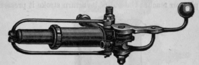
Fig. 237. - Putnam's Syrup Gauge.
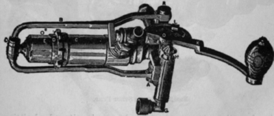
Fig. 238. - Slocum Syrup Pump.
To operate the gauge: first, regulate the supply of syrup by placing the pin in the proper hole, pull the handle F to the right; this will cause the plunger to move in the opposite direction and a vacuum will be produced in front of the plunger, causing a poppet valve to open and admit the syrup from the inlet C. On the return stroke, the inlet syrup valve is closed by the pressure of the syrup in the cylinder, and the outlet syrup valve opened, admitting the syrup to the bottle through the outlet A. When the plunger reaches the end of its return stroke it presses upon the spindle of another poppet valve, thereby opening it and admitting the beverage to the bottle from the inlet B through the outlet A. When plain carbonades are to be bottled, close the cock on the syrup inlet C and work the handle so as to allow the carbonade to enter the bottles as desired.
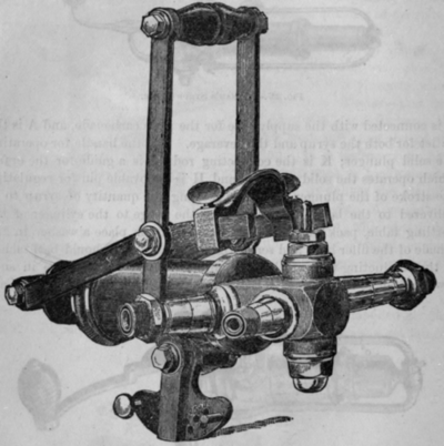
Fig. 239 - Tuft's Syrup Pump.
The next cuts represent English styles of syruping arrangements to facilitate the bottling process and are likewise to be attached to the bottling machine.
The action of ejecting the syrup, and afterwards the carbonated water into the bottle, is done by pulling the handle over, the return motion taking a fresh charge into the pump, and by pressing on the handle the valve is opened and the carbonated water then follows. Should carbonated water only be required, it is only necessary then to press on the handle. The barrel of this pump is of glass; the bucket is made of properly prepared leather and vulcanite; the metal parts are coated with tin and silver.
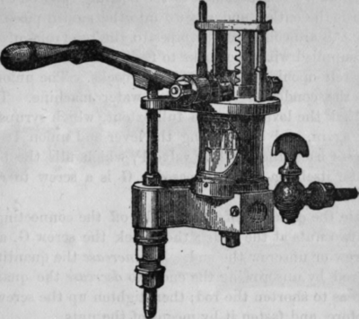
Fig. 240. - English Syrup Gauge.
Continue to:
My Books

