


Stove Valves And Fittings. Hot-Blast Valves
Description
This section is from the "Blast Furnace Construction In America" book, by J. E. Johnson, Jr.. Also see Amazon: Blast Furnace Construction In America.
Stove Valves And Fittings. Hot-Blast Valves
One of the most important details connected with stoves is their hot-blast valves. Long experience with these has now developed a type which is in almost universal use on all stoves, subject, of course, to individual variation in the details. This consists of a mushroom or a poppet valve resting on a water-cooled seat, the valve being supported by a water-cooled stem. The design used by the McCIure Co. is shown by Figs. 148 and 149. Commonly the valve is water-cooled as well as the stem, but in the McClure type of hot-blast valve this is not done, the valves are made solid without water-cooling. The reason for this practice is that if water-cooled valves leak they may discharge a great quantity of water into the hot blast by which it is at once absorbed without showing the least sign, but the effect of this moisture is highly detrimental to the furnace. Moreover, it is claimed by some experienced furnacemen that hot-blast valves last about as long without water-cooling as they do with it, and that it is better to dispense entirely with the danger of leakage even at the price of a somewhat shorter life of the valves.
Fig. 143. Roberts two-pass side-combustion stove - horizontal section.
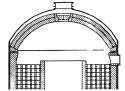
Fig. 144. Roberta two-pass center-combustion stove - vertical section.
The stem, of course, must be water-cooled because it must pass through a gland which is required to make a tight joint on it in all positions. This would be quite impossible with the stem heated to redness as it would be if the valve had been for two hours in the closed position. It was formerly the custom to mount the gland immediately on top of the dome-shaped cap of the hot-blast valve, but more recently the practice has prevailed of putting in a long sleeve, in the present case about 6 ft. long, which is simply a loose working fit on the valve stem and carries the gland on its top.
The air-cooling on the outside of this sleeve prevents the stem from ever getting very warm and the length of the sleeve is such that the portion of the rod which goes inside the hot-blast valve proper when it is closed does not come anywhere near the gland when raised into its highest position. This has brought about a great improvement in the conditions of operating and maintaining hot-blast valves. It will be seen also that a two-inch air connection is provided at the base of this sleeve whereby additional cooling effect may be secured if desired.
The hot-blast valve body is covered with a cast-steel cap as shown, and this top is provided with a flange which makes a water box of its upper surface, and the water discharged into this, after cooling the stem, keeps it in good shape. This is, however, protected by an inside cast-steel cover resting on the brick lining of the hot-blast pipe. In many cases this cast-steel cover is replaced by two large semicircular firebrick tiles with a hole cut out in their center large enough for the valve stem to pass through, these semicircular tiles resting on the brickwork of the lining exactly as shown for the cast cover.
The water-cooled seat is generally made of bronze, cast hollow to provide for a rapid circulation of water through it. In some cases cast-iron seats with a coil of water pipe cast in them are used, but in good modern practice the bronze seats are becoming almost universal. Very recently steel-plate seats of pressed sections welded together have been tried successfully but are not yet in general use.
It will be seen that the hot-blast valve body is cut entirely in two by this seat and held together by clamp bolts which draw together the top and bottom portions of the valve body so as to make a joint on the top and bottom of the valve seat. This arrangement is used in order to facilitate the changing of these seats, which owing to the high temperature and the abrasive action of flue-dust to which they are exposed are subject to heavy wear and must be renewed quickly, since the blast must be off, and the whole furnace stopped, in order to make the change. By slacking off the right and left-hand nuts of the clamp bolts and screwing them out until the flat faces on the end of the straight portion of their shanks engage with the flat faces on the seat rings the latter may be forced apart by an amount slightly greater than the vertical height of the shoulder around the valve seat, and the latter can then be slipped out and a new one quickly inserted. When this is properly centered and the hot-blast valve body drawn back to place, the projecting ring or shoulder around the seat of the upper flange holds it securely in place.
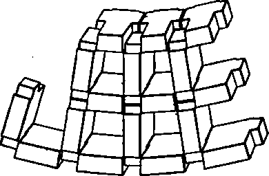
Fig. 147. Isometric view of checkers.
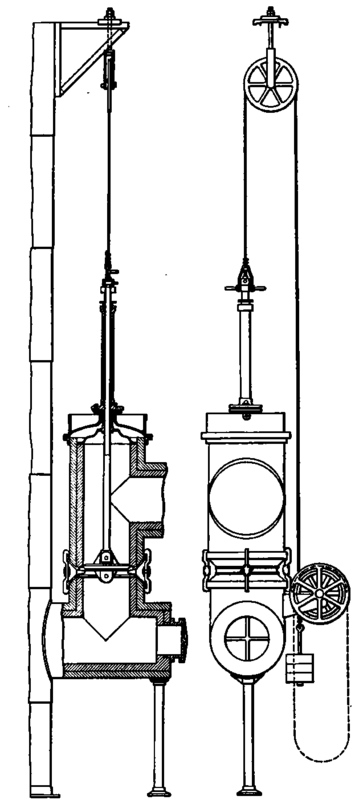
Figs. 148, 149. M'Clure hot-blast valve.
The hot-blast valve is suspended from a rope which passes over a high pulley and back to a drum mounted in bearings bracketed to the side of the hot-blast valve casing. The rope is given two or three wraps around the drum and a counterweight equal to the hot-blast valve and stem is attached to the lower end. A hand-wheel on the drum is provided and with this arrangement the stove tender can raise and lower this valve without difficulty. In order to facilitate changing hot-blast valves, when this becomes necessary, the high pulley is now in some cases placed at the top of the stove. This gives ample height to raise the valve, not only to open it but to lift it clear out of the valve chamber. The high suspension also facilitates swinging the valve to one side in order to lower it to the ground. These are details of much importance when valves have to be changed, since they facilitate doing it quickly. For the same reason the bolts used to bolt the outside cap to the hot-blast valve casing should be key bolts, or else the bolt holes should be slotted to the outside so that as soon as the bolt is loosened it may be removed without unscrewing the nut all the way.
Continue to:


My Books

