Some Plumbing In Boston
Description
This section is from the book "American Plumbing Practice", by The Engineering Record. Also available from Amazon: Plumbing: A working manual of American plumbing practice.
Some Plumbing In Boston
(Published In 1889.)
Some interesting plumbing has recently been done by Henry Hussey & Co., of Boston, in a large building in that city, and we illustrate seme of its details from sketches recently made by a member of our staff.
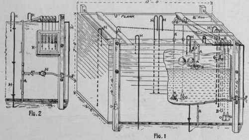
Figure is a view of the main attic tank. It is filled by pumping or from the street pressure, through the two ball cocks on the 1½-inch brass pipe A, and overflows through the 1½-inch pipe B. .
FTG.4
The pipe A, where it comes down inside, is attached to the side of the tank by the foot E, which is soldered to the copper lining of the tank, as will be seen by the sketch. The two ball cocks are attached to branches from the tee D. It is intended ordinarily to keep the tank about two-thirds full of water, as shown, but in summer it is used temporarily to supply water for the infrequent use of the freight elevator, and it is arranged to be then filled up to the top of the overflow pipe B. The ball cocks are then removed from tee D to tee F, and the plugs now in the branches of the latter are transferred to tee D and the overflow outlet at G is closed.
H H, etc , are ½-inch brass vent pipes from the heating boiler, main lines, etc. I is the waste pipe for emptying the tank. J is its valve, which can be raised and opened by the chain K. Valves similar to J are at O O, etc., controlling the supply to the various pipes; lead weights are attached to the chains to insure the closing of the valves.
SOME PLUMBTNG IN BOSTON, MASS.
Figure 2 shows the face of the tank, which is broken away in Fig. 1. The tank supply through pipe A will, if the key valve N be opened, supply the elevator through the 1½ inch brass pipe P.
R is a locked glass case containing the handles 1, 2, 3, 4, and 5, of the chains from supply valves J O O O O, Fig. 1. When the handles are pulled down, as 1, 3, and 5 are, their valves are opened. When raised, as are 2 and 4, their valves are closed.
Figure 3 shows the hot-water boiler A in the basement that supplies hot water to the kitchens, bathrooms, etc., throughout the house. It is jacketed with asbestos, and contains a coil of brass pipe which receives live or exhaust steam through pipe B, and returns it through the 2-inch brass pipe C to the trap D and thence through the i-inch iron pipe E to the boiler.
T is a thermometer.
F is the cold-water supply pipe.
H and H are hot-water supply pipes and G is the hot-water return circulation pipe.
I is the 1½ inch brass sediment pipe to empty the boiler.
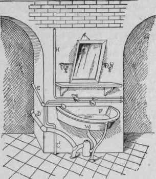
Figure 4 shows the sink in the boiler-room. It is neatly supported by a frame made of polished brass pipes nicely curved.
H is the hot, and C is the cold-water pipe; W is the waste, and D the trap vent pipe.
E is a waste pipe from the receiver into which all the safes and refrigerators in the house are drained.
Continue to:
My Books

