Pipe Bending And Elbows - Continued. Continued
Description
This section is from the book "Plumbing Practice", by J. Wright Clarke. Also available from Amazon: Modern plumbing practice.
Pipe Bending And Elbows - Continued. Continued
After the piece of lead has been lined out as in Figure 47, measure the distance A A' on Figure 46, and mark off the same distance on A A', Figure 47, on both sides of the lead. Then measure B B, as seen in Figure 46, and mark off on B B', Figure 47. C C is the same as B B', so a line can be drawn across at right angles. Now measure off and transfer E E', and as D D' is the same as E E' a line can be drawn across these also. Draw lines connecting the points, and one half of the elbow is shown. Now draw the line X' Y' and with the compasses transfer the distances already marked, on the other side of it; draw a parallel line about 3/8-inch away for the other side to socket into, and one of the elbows is set out. Now with the compasses take off the distance B' B" on Figure 46, and measure B' B" on Figure 47. Without altering the compasses, measure all the other points on their respective lines. Draw X" Y" and transfer as described for the other; allow a piece for socketing; cut out and fold up. In this case the soiling and shaving should be done after it is folded up, as in working the angles up to sharp arrises it would get scratched and tarnished and so require re-doing. Some of my readers, no doubt, will say - Why all this trouble to make a double elbow? Would it not be much easier to make the pipe first and then saw out V pieces and so get the required piece of work? I answer, yes ! but my reason for giving the information is to get apprentices and others who now look upon geometry as dry work to take an interest in it, and see the value of it, and so be able to work to rules instead of by guesswork.
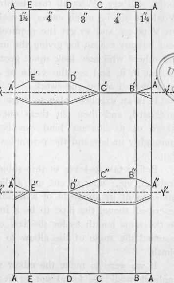
Figure 47.
It is an excellent plan to draw the illustrations here given on cardboard, and then cut them out and fold them up, and then others of a different kind can be attempted, so as to get to thoroughly understand the principles and apply them in the workshop.
Before taking leave of this subject, we will consider one more problem, viz.: how to cut out a piece of lead to make a double elbow to fit in an angle of a building, to get over the plinth as described above, the pipe to be 4 inches and square, the ends to be the same length as for the last one. In the last problem we assumed the angle of the elbow to be 1350 to fit the top of the plinth.
If we were to make the elbow we are now considering at that angle it would be found not to fit the angle of the same plinth, and a moment's thought will lead to the conclusion that the angle must be more acute or sharp. To find what the angle should be we must first find what is the distance that one angle of the building is from the other, and to do this we must first draw a plan of them. Let A A' A, Figure 48, represent the face of the wall of the building, and B B' B the face of the wall which constitutes the plinth. If they are drawn 6 inches apart to represent the projection we can then measure B' A', and so get the distance those two points would be if horizontal or on the same level. This must not be accepted as the length between the heel of one elbow and the throat of the other; to get that, and also the angle of the elbows, we must next proceed to set out an elevation showing the face of the two walls, and the top of the plinth at an angle of 135o.
If the distance B' A' in Figure 48 is now drawn in front of the part representing the plinth, at C D E F; project the front and side angles as shown by dotted lines drawn parallel to those representing the back corner of the pipe, as stated. Now set out the piece of lead, which should be 16 inches wide, as follows: 2 inches from one edge draw a parallel line, then three others each 4 inches from the one preceding, which will leave 2 inches to complete the other side. Supposing the seam is to be in the centre of the side E F, Figure 49, mark off the distance E to where it is intersected by the mitre on E in Figure 50, then transfer C in the same manner, then D, then F, which is the same as C, then mark on the edges of the lead the distance from the end to the mitre of the part forming the seam; draw an X' Y' through E and transfer the distances on the other side as before explained. Measure the distances for the other elbow, as explained for Figures 46 and 47, and on folding the lead it will be found to be the required angle and to fit in the position for which it is intended. If the angles are going to be wiped, the usual 3/8-inch must be left on one side for the other to socket into. If the soldered seam is not wanted to be seen, it can be soldered on the back angles, where it would be out of sight, or in the case now before us, it could be soiled and shaved and soldered inside either with a copper bit and fine solder, or with ordinary plumber's solder, and "wiped" out. If the ends of the elbow were longer this would be more difficult to do, as a man could not get his nand inside; but in some cases, where the pipe is not too long, a cloth can be fastened on the end of a piece of wood, commonly called a " cat's paw," and wipe out the angle in that way.
Figure 49, as shewn by thick line and the top end connected to angle A', we get the required distance and angle at the same time, and this forms the back corner of the pipe. We next proceed to draw a section of a 4-inch square pipe with its diagonal at right angles to the fine A A', Figure 49, as shown
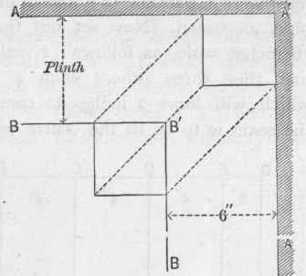
Figure 48.
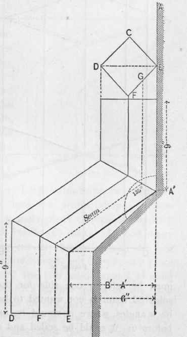
Figure 49.
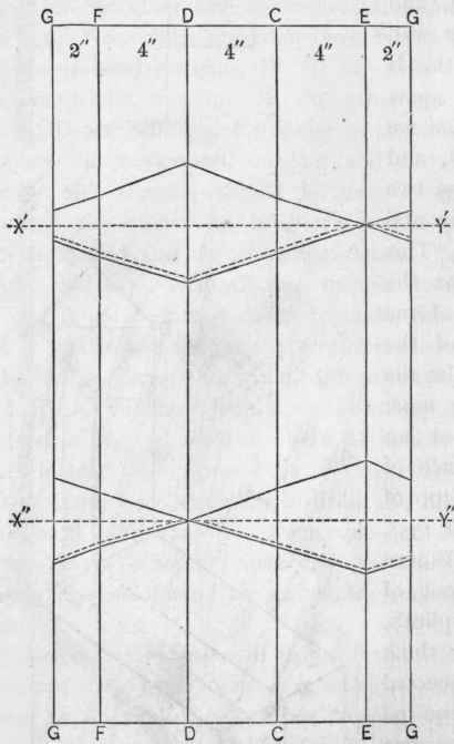
Figure 50.
It is possible to make bends on round pipes and then work them into a square section afterward, as illustrated, Figure 51, on looking at which it will be seen to have bends, in distinction to what we have hitherto called elbows.
It is not at all difficult to make them. For a 3-inch square pipe a piece of 4-inch round pipe should be used, and great care taken in making the bends to keep the lead as equal in substance as possible.
After making the bends on the round pipe a small hand dummy should be used to slightly raise the parts intended for the angles, and then the sides dressed in and the arrises worked up on the outside.
It is necessary to make a chalk mark on the pipe where the angles should come, as in the absence of these guides, it will sometimes occur that the bend gets twisted, and when this happens it requires a good deal of trouble to get it into the proper shape. These bends can only be made when a short piece of pipe is required, so that a small hand dummy will reach any part. A good many similar bends are made by cutting out two pieces of lead the size and shape of the sides of the required bend, and then bend a piece of lead to fit the front and " wipe " the two inside angles forming the front; afterwards bend and fit a similar piece on the back side and solder the two back angles on the outside. If the bend has a moulded front it is much better to have a wooden block made the shape of the required bend and the same size as the pipe. Cut out a piece of lead equal in width to the front and two sides of the block, allowing about 1 inch extra on each side for turning round the back side for nailing and fixing. Lay this piece of lead on the block and work down the sides; if there is any moulding to work, the lead must be tightly fixed, or else it will continually keep rising, and it is important that when once the lead is worked into the moulding it should be kept there, as if it gets moved ever so little, and a fresh chasing made, there will be so many tool marks made, as to be almost impossible to get them out again; and, in addition, the lead generally gets considerably reduced in substance if worked two or three times. After the bend is worked, take it off the wood block, trim the edges, and bend and solder a piece on the back side.
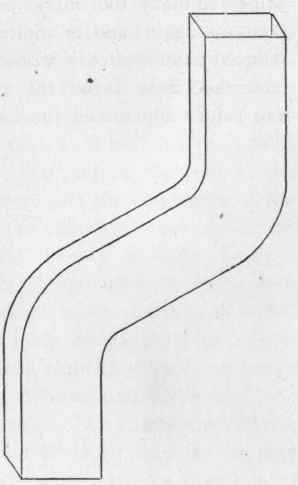
Figure 51.
Continue to:
My Books

