Chapter VI. Pipe Bending And Elbows - Continued
Description
This section is from the book "Plumbing Practice", by J. Wright Clarke. Also available from Amazon: Modern plumbing practice.
Chapter VI. Pipe Bending And Elbows - Continued
One of the most necessary things for a plumber to have a knowledge of is geometry. He may not have time to take up Euclid to make a thorough study of it, but that is no reason why he should not have an elementary knowledge sufficient to be of use to him in his trade. For instance, instead of making templates for his bends, he can set them out as described in last chapter. If he wants to make a taper pipe out of a piece of lead, he can cut it out and prepare it for soldering before bending it into the required shape. He can also cut out pieces of lead to fit any part of a roof, or a spire, either when conical or octagonal, or any other number of sides. This part in geometry is called the development of surfaces, and is really very simple, although generally looked upon as very difficult. He can also take a piece of sheet lead and cut it out the required shape for an elbow, and then soil, shave and fold it up ready for soldering without any previous fitting.
Supposing that he wants to make an elbow out of a piece of lead, at an angle of 1200, and the pipe to be 4 inches in diameter. He first of all cuts the lead out the required size. If the elbow is to be, say, 12 inches long each side of the heel, we have one dimension, so the lead must be 2 feet long. The width we arrive at by multiplying the diameter, 4 inches, by 3.1416, but for those who do not clearly understand decimals, multiply by 3 1/7. So we get 4 inches by 3.1416, which gives 12.5664 inches, or a little over 12 1/2 inches; so to make the required elbow we want a piece of lead 2 feet long, and, say 12 5/8 inches wide. Now, take a pair of compasses with a pencil point, and set them to a radius of half the diameter of the intended pipe, viz., 2 inches, setting them a little full to allow for thickness of the lead, and describe a circle on a clean board with the face well chalked, so that the lines will be clear and distinct (or if no board or pencil compasses are to be had, a remnant of sheet lead napped out smooth will do as well, and use a pair of pointed compasses). Now lay down the compasses without shifting them, and draw two diameters at right angles to each other, as A B and C D, Figure 44. Take up the compasses, and with A B C D as centres, cut the circle as shown, which will divide it into twelve equal parts. Now draw the pipe full size, and at the required angle immediately beneath the circle, as shown in the illustration, Figure 44, and project the divisions of the circle on to it, as shown by dotted lines.
On looking at the illustration it will be seen that these dotted lines appear to be closer together at the sides than in the centre, but on looking at the circle they will be found equi-distant. So for distances apart we must measure off the circle (or, what would be called in geometry, the sectional elevation), but the distances on what would be called the plan, as shown by the dotted lines, represent the correct length or distance from the end to that part of the pipe cut by the niche, or mitre, a b. Now take the piece of lead which has been prepared, and divide it lengthways with a chalk line into twelve equal parts, by first setting the compasses to the distances on the circle, and stepping it across the end, as shown by Figure 45.
The compasses should be set a little full to allow for the rise of the circle between the points. Now, as a rule, the seam of the pipe should be on the side, and as D is represented in that position, we will take that as the seam, so that D D on Figure 45 will be the parts that will come together in the seam. Take the compasses and put one leg on D and the other on the other extremity of the line cut by the niche on Figure 44, and transfer it to the line D D in Figure 45 on both sides of the lead. Measure off the next line I, and transfer it in the same manner; then J, and then A. Now, supposing that the plan of the pipe was transparent, the line J also represents K, so that distance must be transferred on to line K in Figure 45. I also represents L, and D, C, and so on. To save time and avoid altering the compasses as much as possible, it will readily be seen that two distances can be marked each time in some cases. After these distances have been marked off, they can be joined together by freehand, and this represents one-half of the intended elbow.
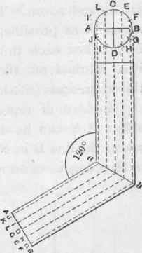
Figure 44.
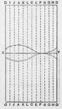
Figure 45.
Instead of repeating these measurements from the other end, a line X Y can be drawn across the piece of lead at right angles to where the line B in Figure 45 is cut, and then by placing one point of the compasses on it, and the other point on the lines as marked, the distances can be transferred to the other side, and then joined by freehand as described before. Draw a line parallel and about 3/8-inch away on one of the sides for the other one to socket into when folded up. Cut out the piece of lead enclosed by these lines, soil, shave, and fold it up, and it will be found to fit and be the required angle. It would be much better and fit truer, if twice the number of longitudinal lines were used, but they are not shown in the illustration, as it must, of necessity, be drawn to a small scale. The foregoing directions will be more readily understood if it is imagined for the time that instead of the pipe being round, it has the same number of sides as denoted by the longitudinal lines. This will, perhaps, be made plainer by studying the following illustrations, which show how a piece of lead would require to be cut to form a double elbow made out of square pipe.
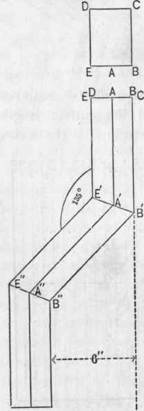
Figure 46.
Supposing that this double elbow is wanted for a rain-water pipe and to fit over the plinth or projection round the base of a building which stands forward 6 inches beyond the superstructure, that the ends of the elbow are to be 9 inches long, the pipe itself 4 inches by 3 inches, and the solder seam to be in the centre of the side. First of all, set it out as before advised to the required angle, say 135o, see Figure 46, and measure the size of the piece of lead required. It will be found to be 2 feet 4 3/4 inches x 1 foot 2 inches; after it has been squared, and the edges planed straight, make chalk lines down it as shown by lines in Figure 47. As the seam is to be in the centre of the side, the first line will be 1 1/2 inch in, which is equal to half the side of 3 inches, the next line should be 4 inches from the first, for the front, the next 3 inches from the second for the other side, then 4 inches for the back, 1 1/2 inch will be left to complete the other side. These four lines represent the four angles of the pipe. It is a common practice when making square pipe to run the point of the shavehook down these lines, to plough a piece out of the lead, so that the angles turn up true, and the arrises are sharp without any trouble dressing them up. Although when finished, the pipe or elbow looks neat and free from tool marks, still the practice should be condemned as the lead is much weakened, and it is a common occurrence for the angles to split because of this.
Continue to:
My Books

