Distributing Manifolds
Description
This section is from the book "Principles And Practice Of Plumbing", by John Joseph Cosgrove. Also available from Amazon: Principles and Practice of Plumbing.
Distributing Manifolds
In piping a building for water supply some system should be observed whereby all rising lines will start from some common point centrally located. By observing such a system, all supply lines can be controlled by valves located at one point of the building; provision can be made to drain the pipes when the water is shut off; a better distribution of water will be effected, and systematizing the work will so simplify the construction that it can readily be understood and more cheaply installed.
In dwelling houses, branches to the several fixtures or groups of fixtures should be taken from the hot and cold water supply mains at some convenient point in the kitchen. A suitable place for the grouping of valves, branches and drains is over the kitchen sink, as shown in Fig. 93. Another convenient place is on the ceiling or back of the range boiler, as shown in Fig. 94. This system places control of the entire water supply under the care of the cook, who can quickly cut off the supply of water from any branch that is out of order.
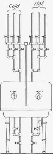
Fig. 93
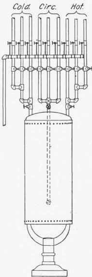
Fig. 94
In the installation of water supply systems in large buildings, the distributing manifold is usually located in the basement or cellar, and a separate line of supply pipe taken from the manifold to supply each rising line and separate group of fixtures in the building. Manifold headers for hot, cold and circulation pipes are shown in Fig. 95. When used in connection with low pressure supplies the air chambers are usually made of capped iron pipe located at the ends of the manifold or at the center directly over the supply inlet to the headers.
In high-pressure water supply systems, a drum or cylinder air chamber is generally used in connection with the cold water manifold header. This method of installation is shown in Fig. 96. The cold water supply main connects to the air chamber near the bottom so as to entrap the air within. Connections from the air chamber to the distributing manifold are also taken from the bottom of the cylinder so air cannot escape in that way. In other respects the manifold header is connected in the same manner as low-pressure manifolds. In extremely tall buildings, where the upper floors are supplied from tank pressure, while the lower floors are supplied direct from the city mains, two sets of hot, cold and return distributing manifolds are installed, one set for each source of supply.
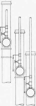
Fig. 95 - End Elevation
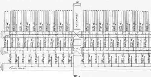
Fig. 95
Continue to:
My Books

