Fire Lines
Description
This section is from the book "Principles And Practice Of Plumbing", by John Joseph Cosgrove. Also available from Amazon: Principles and Practice of Plumbing.
Fire Lines
System Of Installation
Fire lines are now generally-installed in all large buildings. A typical arrangement of pipes for fire service is shown in Fig. 106. In this system the lines are cross-connected, so that either the fire pump, the house pump, or both pumps can supply water in case of fire. A house tank on the roof keeps the lines full of water and provides a temporary supply while the pumps are being started. Branch lines extending through the building walls to the street terminate with Siamese twin connections, through which water from street hydrants or fire engines can be forced into the system. The fire system is well supplied with soft seat check valves, so that water supplied from one source cannot be lost through other outlets. A check valve in the line of pipe connected to the tank prevents water from filling and overflowing the tank when supplied from pumps or twin connections. Checks in the lines leading to the twin connections prevent the loss of water from these outlets when water is supplied from either the pump or the tank, and check valves in the pump pipe relieve the pump valves of the pressure of water in the system. Emptying pipes are provided to drain the entire system, and separate pipes are provided to empty and thus prevent water freezing in the portions of pipe between the check valves in the cellar and Siamese twin connections in the street. At each floor of the building 2 1/2-inch outlets are left, to which are attached soft seat angle hose valves with 50 to 75 feet of underwriters' linen hose coiled on a reel or folded on a rack.
Sizes Of Standpipes
For fire lines standpipes should be proportioned to the number of hose outlets they supply. The size of opening in hose nozzle for hose of 2 1/2 inches diameter seldom exceeds 1 1/4 inches in diameter, and if allowance of the sectional area of a 2-inch pipe be made for each hose outlet in the building, both sufficient volume and pressure will be provided to throw an effective fire stream when all the nozzles are being used.
Range Of Fire Streams
The extreme distance water can be thrown both horizontally and vertically, and the distance the streams will be effective for fire purposes under different heads and through different sizes of nozzles, are shown in Table XXXIX.
Table XXXIX - Range Of Fire Streams - Pressure At Nozzle Given, Showing Pressure At Hydrant, Amount Of Water Discharged And Distance Thrown (Extreme Drops) Through Smooth Nozzle, Using 100 Feet 2 1/2-Inch Rubber Hose. Compiled From Actual Tests By John R. Freeman, Hydraulic Engineer, Boston, Mass
Pressure at Nozzle, Pounds .... | 30 | 40 | 50 | 60 | 65 | 70 | 75 | 80 | 85 | 90 | 95 | 100 | |
Pressure at hydrant . . . | 32 | 43 | 64 | 65 | 70 | 75 | 81 | 86 | 92 | 97 | 102 | 108 | |
Gallons per minute . . . | 90 | 104 | 116 | 127 | 132 | 137 | 142 | 147 | 151 | 156 | 160 | 164 | |
1/2-inch Nozzle | Feet thrown horizontally, d | 48 | 56 | 65 | 68 | 70 | 72 | 75 | 76 | 77 | 80 | 82 | 85 |
Feet thrown horizontally, c Feet thrown vertically, b . | 96 | 112 | 125 | 136 | 141 | 145 | 149 | 153 | 157 | 161 | 164 | 167 | |
48 | 60 | 67 | 72 | 74 | 76 | 78 | 79 | 80 | 81 | 82 | 83 | ||
Feet thrown vertically, a . | 59 | 78 | 98 | 104 | 109 | 114 | 119 | 123 | 126 | 129 | 182 | 134 | |
Pressure at hydrant . . . | 37 | 50 | 62 | 75 | 81 | 87 | 94 | 100 | 106 | 112 | 118 | 125 | |
Gallons per minute . . . | 161 | 186 | 208 | 228 | 237 | 246 | 255 | 263 | 274 | 279 | 287 | 295 | |
1-inch Nozzle | Feet thrown horizontally, d | 55 | 66 | 76 | 83 | 86 | 89 | 92 | 95 | 96 | 98 | 100 | 102 |
Feet thrown horizontally, c Feet thrown vertically, b . | 109 | 133 | 152 | 167 | 173 | 179 | 184 | 189 | 198 | 197 | 201 | 205 | |
51 | 64 | 73 | 79 | 82 | 85 | 87 | 89 | 91 | 92 | 94 | 96 | ||
Feet thrown vertically, a . | 63 | 88 | 101 | 117 | 124 | 130 | 135 | 140 | 144 | 147 | 150 | 152 | |
Pressure at hydrant . . . | 42 | 56 | .70 | 84 | 91 | 98 | 105 | 112 | 119 | 126 | 133 | 140 | |
Gallons per minute . . . | 206 | 288 | 266 | 291 | 303 | 314 | 325 | 336 | 346 | 356 | 366 | 376 | |
1 1/8-inch Nozzle | Feet thrown horizontally, d | 58 | 71 | 81 | 89 | 92 | 95 | 98 | 101 | 105 | 107 | 109 | 212 |
Feet thrown horizontally, c Feet thrown vertically, b . | 115 | 142 | 162 | 178 | 185 | 191 | 197 | 203 | 209 | 214 | 219 | 224 | |
52 | 65 | 75 | 80 | 85 | 88 | 90 | 92 | 94 | 95 | 97 | 99 | ||
Feet thrown vertically, a . | 64 | 84 | 104 | 122 | 130 | 186 | 142 | 146 | 150 | 158 | 156 | 158 | |
Pressure at hydrant . . . | 49 | 65 | 81 | 97 | 105 | 118 | 121 | 129 | 137 | 145 | 154 | 162 | |
Gallons per minute . . . | 256 | 296 | 331 | 863 | 377 | 892 | 405 | 419 | 432 | 444 | 456 | 468 | |
1 1/4-inch Nozzle | Feet thrown horizontally, d | 60 | 74 | 85 | 93 | 96 | 100 | 108 | 106 | 110 | 112 | 115 | 118 |
Feet thrown horizontally, c Feet thrown vertically, b. | 119 | 148 | 169 | 186 | 198 | 200 | 207 | 213 | 219 | 225 | 231 | 236 | |
53 | 67 | 77 | 85 | 88 | 91 | 98 | 95 | 97 | 99 | 100 | 101 | ||
, Feet thrown vertically, a . | 66 | 86 | 107 | 126 | 133 | 140 | 145 | 150 | 154 | 157 | 159 | 161 | |
a equals average height reached by highest drops in still air.
b equals greatest height stream is effective for fire purposes.
c equals greatest distance of farthest drops in still air at level of nozzle.
d equals greatest distance stream is effective for fire purposes.
A Siamese Twin Connection is shown in Fig. 107. A flap valve, a, closes one opening when pressure is applied to the other, and stands open as shown in the illustration when water is being forced through both openings.
Fire Hose
The most suitable hose for use in buildings is underwriters' linen hose. It will withstand almost any pressure likely to be subjected to and, being flexible, can be neatly coiled or folded into a very small space. The size of hose generally used for this purpose is 2 1/2 inches diameter.
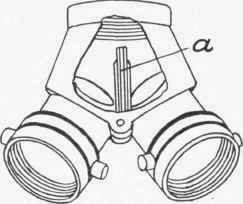
Fig. 107
Hose Reels
Each length of hose should be neatly folded or coiled on a rack or hose reel provided for that purpose and attached to the wall or fire pipes close to the valve outlet. Hose racks crease the hose at each fold and for that reason are not so desirable as hose reels. A very satisfactory swing hose reel is shown in Fig. 108. It is supported from the fire stand-pipe by a hinged clamp that permits the reel to turn in many directions.

Fig. 108
Continue to:
My Books

