House-Drains (Continued). Disconnection And Ventilation. Part 2
Description
This section is from the book "Principles And Practice Of Plumbing", by S. Stevens Hellyer. Also available from Amazon: Principles and practice of plumbing.
House-Drains (Continued). Disconnection And Ventilation. Part 2
Fig. 169. - Section of a 6 in. Ventilating Drain-Syphon, with Tapering Pipes, and Brick Air-Shaft.

Fig. 170. - Section of the " Drain - Sentinel " Disconnecting Trap.
9. A manhole cover is shown at e, but a grating, where circumstances admit of it, can be fixed instead of an airtight cover. The advantage of a solid cover, apart from other reasons, is that it prevents dirt and various other things from falling down upon the benches on the shelving sides of the manhole bottom, to become a nuisance.
There are many so-called air-tight covers now in the market, but in testing drains with smoke I have often found that, though they are designated " air-tight," they are not smoke-tight. It is better to fix two sets of covers rather than rely upon a cover which is not absolutely airtight.

Fig. 171. - Section of "Drain-Sentinel" Disconnecting- Chamber.
10. Where a manhole is built over the disconnecting-trap inside a house, or in a cellar with its doorway opening into the basement, the manhole should be made both absolutely air-tight and water-tight. Its interior, though built of good bricks, should be well cemented on all sides, and highly faced with a trowel. The access cover should be absolutely reliable.
11. Fresh air should be admitted at the upper part of the manhole, as shown at A2, and the mouth of the induct, A1, fixed where it would be least likely to be offensive in case of any reaction in the air-current.
12. A mica-valve would often be necessary (fig. 116, Chap. XXVII.). Some authorities prefer the mica-flap to stand open a little, so that fresh air may pass into the induct-pipe without any effort. But I prefer, where it is necessary to fix a mica-valve at all, that the mica-flap should entirely seal over the mouth of the induct-pipe when at rest. The current of air for fifty-five minutes out of sixty, where the ventilation-pipes are properly arranged, will find good ingress, and the tight-fitting flap prevents back-draught better than the open one.
I claim the credit of both designing and introducing the first mica-valve for fixing over the mouth of a fresh-air induct to soil-pipes and drains. I know that the late Mr. Eassie thought that he was the first to introduce this most useful appliance; but I asked him to tell me where he had the first one made, and then we could soon settle the question, and this did settle it, not only to my own satisfaction, but to his as well. When it occurred to my mind that "foot-ventilation" to a soil-pipe would be a good thing, I had a small pipe, a 2 in. pipe, fixed for the purpose, and then it was that I found that some contrivance was necessary for preventing down-draught or back-draught, and though I sent to all the people in London who would be likely to have any knowledge of a mica-valve for such a purpose, had there ever been one made, I could find nothing, and had one made up specially, which I believe is still working, though the mica has had to be renewed.
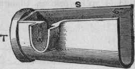
Fig. 172. - View of Channel-Pipe, WITH A RIGHT-HAND Inlet.

Fig. 173. - Plan of Channel-Pipe, with Inlet on each side.

Fig. 174. - Section of Cast-Iron Trap, with turn-round Inlet, and Head for Pipe-Shaft.
13. My patent "Combination" disconnecting-trap (fig. 174) is made in cast-iron of great strength for connection to cast-iron drain-pipes by caulked lead joints. The connecting-piece, B, can be turned round upon the trap to suit any angle, and the oval-shaped doorway, H, affords access to the trap for introducing a stopper into the end of the drain, at e, for charging the house-drain with water for testing purposes, etc. The connecting-piece, b, can be fixed one upon another to allow several branch drains to discharge into one disconnecting-trap.
Fresh air may be admitted through a grating fixed over the pipe-shaft, as shown in figs. 167 and 169, or the top may be sealed down by a stopper, with a cover-plate over it, and fresh air brought into the pipe-shaft, as shown at A, fig. 168, from the most suitable place, with or without a mica-valve, as circumstances required.
14. By the use of a cast-iron disconnecting-trap, as shown in fig. 174, the trap could be made to stand in a brick-built manhole-chamber, and be inspected at any time without exposing the house to drain air; and, as all the joints to the trap with the drain-pipes would be made with metallic lead, there would be no risk of unsoundness in the connections.
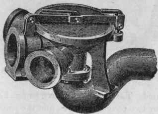
Fig. 175. - Scott-Moncrieff's Cast-Iron Trap.
15. Fig. 175 illustrates Mr. Scott-Moncrieff's patent lever-locked cast-iron inspection-chamber and trap, for receiving several drains, for connection by caulked lead joints. And fig. 176 shows another form, combined with trap, inspection-chamber, and surface cover and frame. The illustrations speak for themselves.
16. In figs. 177 and 178 illustrations are given of Messrs. John Smeaton, Son, and Co.'s cast-iron manhole and trap combined. The cover, as shown in fig. 177, is secured in its place by two cover-fasteners, and the packing between the cover and the manhole consists of india rubber.
Continue to:
My Books

