Form Details And Practical Designs. Part 3. Part 5
Description
This section is from the book "Practical Concrete Work for the School and Home", by H. Colin Campbell. Also available from Amazon: Practical concrete work for the school and home.
Form Details And Practical Designs. Part 3. Part 5
Plate 28 is merely an elaboration of preceding designs.
Plate 29 shows forms for combined pedestal and vase. The various parts are a, b, c, d, e, and f. Part a can be made of one piece as shown or may be built up from 4 pieces of thin stuff nailed together to form a molding. Part e may be formed of one piece or likewise built up, two pieces of board and a piece of 1/4 inch round molding being then used. Mitered joints are made after parts a, b, c, d, and e have been assembled with screws. Parts b and d are braces and may be made either as shown or of angle iron. The pedestal is cast bottom side up. It may be used without a vase as a flower urn or with a plate on top may serve as a sundial and pedestal.

Section through Center of Form for Pedestal.

A concrete well curb and platform goes a long way to prevent surface filth from getting into the home water supply.
Plate 30 shows details of a design for flower box. The exterior form consists of parts a, b, c, and d. Part a is beveled at the upper end and rabbeted at the lower end. This rabbet forms a cornice around the top of the finished object. Part c consists of a piece of 1/4-inch round attached to the part b. Part d consists of thin narrow strips of wood attached to part a so that they form a Greek key. These strips should be tacked on with small brads to prevent splitting and also to prevent defacing the exposed surface. All edges of these strips should have a slight draft to make form removal easy. The box is cast bottom side up. Mortises formed in the bottom of the concrete box are made by part e which is held in place in the form by means of cleat f extending to the sides. The core is of a pattern previously described. Reinforcement may be wire mesh or expanded metal. Care should be taken that mortises are placed in the exact position shown.

Section through center of Flower Box Form.

Plan of Form with Top removed.

This concrete spring casing serves also as a stock drinking trough in the pasture lot.
Plate 31 gives details of legs or standards for supporting the box shown in Plate 30. These forms consist of parts g, h, j, k, I, m, n, p, q, r, and s. The bottom edges of parts h and p are shaped by the worker and the top rabbeted as shown. Part h has piece .s and small strips r attached to the inner face so as to form ornament. Parts q have strips r attached to mold the fluting. Part p is cut out at the top at the center to form a bracket on inner side. The form for this bracket consists of pieces m, n,
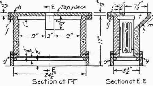

Plan of Top Piece and /. The bottom sides of pieces n are cut to the bevel shown and piece / is nailed to the beveled surface of two pieces forming the bottom of the bracket. Piece m is nailed between the two pieces n. The side faces of the bracket form should be given slight draft to make withdrawal easy. Top piece k is placed on top of form after concrete has been brought up to surface. The opening t is then filled with concrete. Care should be taken to have this opening in a position corresponding with mortise in the bottom of the box.
The details of assembling this box on its supports are shown in Plate 32.
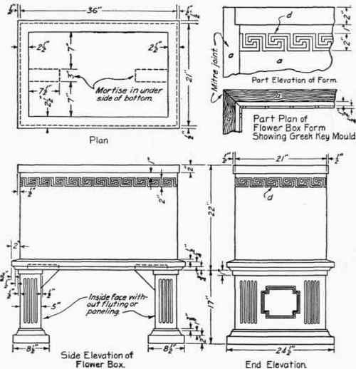
Plate 33 shows details for a garden bench. The form for the seat slab consists of part a. This has mitered joints and as assembled is held in position on the workbench by small blocks. Part a when made of the shape shown should always terminate in a small member c. If the curve is brought down to a feather edge the concrete soon slivers off. Mortises are formed by holding part d in position shown by means of cleats e extending across the top of form.
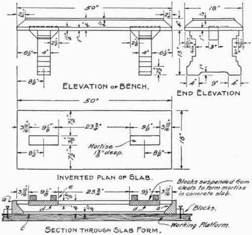
Plate 33A shows forms for the legs of the bench illustrated in Plate 33. These consist of pieces f, g, h, j, k, I, and m. Piece f is cut out from one piece by a band saw and the surface smoothed with sand paper. Brackets are formed by nailing parts h to the sides. Sides are cut out at the top for a bracket. Part j is nailed to parts h. Part t is nailed to the workbench in proper position, the legs right side up. Concrete is placed in the form to the top after which piece k is set in place and opening / filled with concrete. Care should be taken to have tenon / and mortise d, shown in Plate 33, in proper relative position.

Plan op Form with Top Piece removed.
PLATE 33A

Top View of Bench.
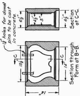
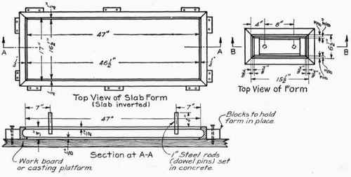
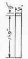
Plates 34, 35, and 36 contain further suggestions for a more ornamental garden seat. Forms in general are like those shown in Plates 33 and 34. Instead of using brackets on legs, dowel pins and a mortise joint are used for assembling legs and seat slab. The legs are cast right side up. A greased rod is suspended in the form in proper position to make hole in the concrete for dowel pin. Corresponding holes are formed in the bottom of the seat slab. In assembling the bench the dowel pins are first set in the bottom of the slab while it is still bottom side up and secured in place by a cement grout. When this has hardened, holes in the top of the legs are filled with grout and covered with a bed of mortar. The slab is then placed in position. The dowel pins enter the grout filled holes and are thus firmly held.

A still more elaborate garden seat is shown in Plates 37, 38 and 39. A front elevation and sectional plan of the completed product is shown on Plate 37. The seat is made in four parts-the back, the two end columns and the seat slab. An ornamental vase or flower pot may be placed at the top of the columns as shown in elevation, if desired. The back and center leg are cast in one piece, the form for this being shown in detail in Plate 38.

Sectional Plan.
End Elevation,

Plan of Seat

Detail of Ornament.

Details of Form for Back of Settle.

Section at E-E.
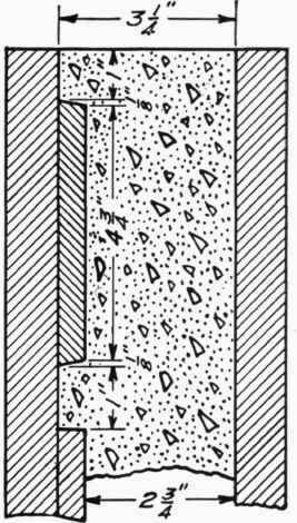
Details of Form for Column "B"
The form should be built so that the concrete may be placed into it from the top and should be clamped or screwed together in such a manner that the forms for the center leg may be removed first. Care should be taken to have the joints of the forms watertight. In work of this nature it is best to have tongued and grooved boards for the large flat surfaces. The forms for the ornamental work at the top of the seat back are shown in detail in Plates 38 and 39. The back must be reinforced with heavy expanded metal or with 1/4-inch bars spaced about 8 inches on centers in both directions. The expanded metal or bars should also extend into the center leg and be securely fastened to the reinforcement in the back.
Section on G-G.
The seat is a simple concrete slab reinforced with heavy expanded metal or 1/4-inch bars placed 4 inches on centers longitudinally. The reinforcement for both the back and the seat should be placed about in the middle of the slab. If desired, the seat may be cemented to the back and legs. The forms for the columns A and B are shown in Plate 39. They are made in a manner similar to forms for pedestals and columns heretofore described. The groove indicated on the drawing should be true and slightly larger than the thickness of the back slab. When the back and columns are assembled, cement grout should be poured into these grooves in order to cement these parts together. All faces of the concrete work should be rubbed down with carborundum brick and water in order to secure a uniform surface and to remove all signs of form joints. At very little additional expense a beautiful surface may be obtained by using white port-land cement and granite or marble screenings which, when rubbed down and polished, gives the appearance of solid granite or marble.
The forms required for this work are only an elaboration of the ones heretofore described for various products, and by carefully following the drawings and using a little ingenuity, they can be built economically and may be used a number of times.
Continue to:
My Books

