Mitring
Description
This section is from the book "Woodworking For Beginners: A Manual for Amateurs", by Charles G. Wheeler. Also available from Amazon: Woodworking For Beginners.
Mitring
A common joint is the mitre (Fig. 568). Its only advantage is that it shows nothing but a line at the angle and the " end wood " is entirely concealed. It is a weak joint at best, even when made by a skilled workman, and is particularly hard for an amateur to make well. The slightest variation in one of the corners of a frame or box throws the whole structure out of shape and in attempting to correct the error the other joints are apt to be opened, and if the whole is finally got together in a fashion it is often after bother enough to have accomplished much good work in some other way.
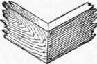
Fig. 568.
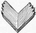
Fig. 569.
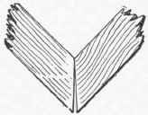
Fig. 570.
The mitre is particularly unscientific for wide pieces used fiat-ways (Fig. 569), as the inevitable expansion and contraction of the pieces is very apt to cause an open joint. If the wood is not quite dry, so that it shrinks, the joint may open permanently toward the inside corner, for when the wood shrinks in width the pieces will become narrower and so separate at the joint, leaving a crack, tapering from the inner to the outer corner. Even if the wood is thoroughly seasoned it will expand and contract more or less. When it expands, the joint will tend to open at the outer corner (Fig. 570). When it contracts it will tend to open, as just shown (Fig. 571), at the inner corner.
Of course there are some cases, as in making a picture frame of prepared "mouldings," when mitring is the only way in which the frame can be put together, and there are some other cases in which it is the most proper and suitable joint, but as a general rule, for amateur work, particularly in framing where strength is a consideration, avoid the mitre. Other and better forms for anything like a box are shown in Figs. 554, 555, 556, 557.

Fig. 571
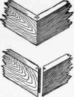
Fig. 572.
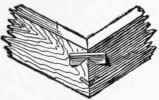
Fig. 573.
The mitre is sometimes strengthened for box work and the like by fitting a spline or tongue with the grain running across and not lengthways of the joint (Fig. 572.) This, properly glued under pressure, makes a good joint and one much superior to the plain mitre. But, though easy to do with machinery, it is a slow and careful job to make such a joint by hand, and if a case arises where you wish it done you had best take the work to a factory, where a circular saw is all that is needed.
The principle of halving shown in Figs. 539 and 543, can also be applied to a mitred joint.
Saw-kerfs are often made (Figs. 573 and 574) into which small strips are tightly fitted and glued. This is a good way and easily done, once having got the mitre properly put together. A combination of the mitre with the joint shown in Fig. 555 is shown in Fig. 575. See also Dovetailing and joints.
To lay off a mitre, or the lines by which to cut the intersection of any two pieces at any angle, a simple way is that shown in Fig. 576. The pieces are laid one above the other at the desired angle. Then the points of intersection are marked on each edge.
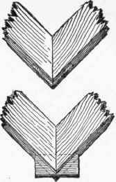
Fig. 574.
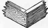
Fig. 575.
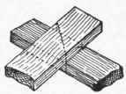
Fig. 576.
Lines connecting these points will give the desired angles for sawing. The square can be used to help in determining the points accurately and to project them to the upper side of the top piece.
Mitre-Box
If you can afford it, an iron mitre-box which will cut at various angles will be very useful. You can make one yourself of wood. You can get a carpenter to make you one for a small sum, but the iron ones are better. See page 90.
Continue to:
My Books

