59. Purlins And Hoppers
Description
This section is from the book "Constructive Carpentry", by Charles A. King. Also available from Amazon: .
59. Purlins And Hoppers
Purlins And Hoppers. (A.) The position and use of purlins are shown at c, Fig. 86. Their lengths may be found by calculations based upon the known length of the plates. If placed as shown in Fig. 86, the cuts at the angles will be square, but if set with the faces upon the same pitch as the pitch of the roof, as at /, the cut will be a hopper cut, explained later. There are several methods of finding the bevels for cutting a purlin. In the miter method, illustrated by Fig. 88, the work should be laid out upon the bevel board, and the bevels transferred with a bevel square, The following key will explain the diagram.
HH (in a) = pitch of common rafters.
A, B, C, D = section of purlin.
RR (in b) = run or plan of hip rafter, showing top view.
B = longest point of purlin.
BE (in c) = line, square with edge at B, and extending around purlin.
AE = distance from the line BE upon the top edge of purlin.
EC = distance from the line BE upon the bottom edge of purlin. A, B, C, D (in c) = cut.
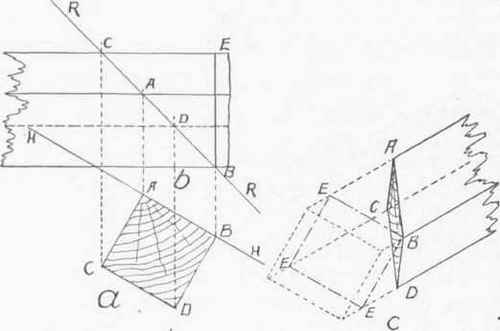
Fig. 88.--Method of laying out Purlins and Hoppers.
The cuts shown in c may be applied to the ends of purlins found by this method, on roofs of any pitch. For any but a square corner, it will be necessary to adapt RR to any angle of plate; hoppers of any angle may be cut by the same method.
A purlin may be cut by using the steel square, if the method illustrated in Fig. 89 is followed. Any flare of purlin or hopper may be cut by this method. The flare of the purlin or hopper should be laid out upon the bevel board, as shown by the diagram, which will be understood if the following key is studied.
F = face cut.
W = width of the face.
B = side cut or butt.
R = run.
A = rise.
M = miter.
The diagram may be applied by the steel square by using the following formulas :
Formula 28. F = W on Bl., R on To. To. = F.
Formula 29. B = Y on BL, R on To. To. = B.
Formula 30. M = Z on Bl., Y on To. To. = M.
In Fig. 90 is illustrated a simple method of laying out the cuts of a purlin, after the roof is partly constructed. The stick from which the purlin is to be cut is laid upon the outside of the rafters, as at ab, or held against them on the inside, parallel with its position when in place. The end should project over the hip rafter as at a, the extreme length of the purlin at point c, coinciding with a straight edge held against the side of the hip rafter as indicated by line de. Draw a line by this method across the sides fg and hi, and connect them across the faces fh and gi, thus completing the lines for the cuts.

Fig. 89. - Second Method of latino out Purlins and Hoppers.

FiG. 90. - Third Method of laying out Purlins and Hoppers.
A purlin is frequently used as the top member of a truss to support a roof in the middle of the rafters, and the struts are so placed as to serve as a partition, as shown at b, Fig. 86.
(B.) Fig. 91 illustrates a method of laying out a hopper graphically. In this diagram, yz represents the bottom of the hopper; ab, the flare of the hopper. Continue the flare indefinitely toward c. From any point on yz, as at d, drop a perpendicular to c; with the radius, de, and d as the center, draw the arc to f; connect f and c; at f is the angle of the face or side bevel. Draw bg square with the flare or face of the hopper. With d as the center, and dn as radius, draw an arc to h. Connect h and c; at h is the bevel of the side or cheek cut.
To find the miter cut of a butt joint hopper use only the dotted lines. Erect the perpendicular bj, which, with the line yz, forms the top view of one corner of the top of the hopper which may be at any angle. Bisect this angle, and continue cd until it meets the bisecting line at k; connect h and k. The angle of the miter or cheek cut is at m.

Fig. 91. - Fourth Method of laying out purlins and Hoppers.
Continue to:
My Books

