Slide-Rest Work In Metal. Part 2
Description
This section is from the book "Turning Lathes", by James Lukin. Also available from Amazon: Turning Lathes: A Guide to Turning, Screw Cutting, Metal Spinning and Ornamental Turning.
Slide-Rest Work In Metal. Part 2

Fig. 11. - Solid Forged Tools.
To make still more clear the principles which guide the action of slide-rest tools, we must recollect that a shaving has to be detached in two directions - viz., from the shoulder a of K, Fig. 12, and from the surface of the cylinder at b. A shaving has to be thus separated at two points, and, to effect this in the best way, it must be cut, and not torn, in either direction. Hence, a perfect tool must evidently have two edges - a front and a side edge; and, as it is the ultimate object of turning to leave a smooth surface upon the work, it is evident that the tool edge which cuts this cylindrical surface must be formed and sharpened as carefully at least as the other, although the latter, as the leading edge, has most of the work to do, and, if there is any difference, needs to be sharpest. This is the double-edge principle, which is often regarded as a sort of scientific theory suited only for amateurs, and of no real use to a workman; but it is not so: it is the fundamental principle of slide-rest tools - easy to understand, and equally easy to apply practically; and no chapter on tools would be complete without an explanation of it. In a round-end tool we may take half the edge as the leader and the other half as the follower; as we may suppose it to be, what it practically is, a double-edged tool of very wide angle, with its extreme point rounded oft'. It is a very common practice to apply a tool end on, whether pointed or rounded (A and B, Fig. 13); but evidently the tools, after having started, cut no further than to the dotted line dividing them centrally, and the part x, x might be cut away altogether. Where, then, is the second edge of the point tool ? Nowhere; and hence the shaving is torn, and not cut, in that direction, and a rough line remains on the surface of the work. Power is also wasted, because it takes more power to tear apart the particles of iron than to cut them cleanly. An "end-on" tool is not, therefore, a scientific one, its proper position being that of M, so as to bring both edges into cut. The same is true of a round-end tool. It is evident that here the extremity is the sharpest part of it, and that the edge gets gradually blunter, as it is situated further and further round the curve; then it is plain, from what has been said, that it should not stand "end on," like x of Fig. 13, because the blunter part at the side is leading. Placed as at C, or bent to the left, it will cut much better. It is never quite satisfactory, owing to the sharpness of edge varying all round the curve, but it is a useful tool which is sure to find a place in every workshop.
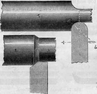
Fig 12 - Slide-rest Work.
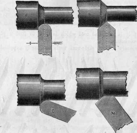
Fig. 13. - Principle of Double Edges.
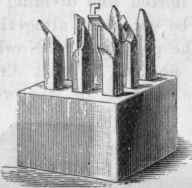
Fig. 14. - Set of Tools for Slide-Rest.
The variously formed slide-rest tools ordinarily supplied in complete sets are illustrated together in Fig. 14, set up in a block, and in Fig. 15 they are shown separately; and it would be difficult to devise other shapes, as there can hardly be any work, hollow or otherwise, which one or more such tools will fail to cut. The three on the right hand of the second row are, however, not solid tools, but bars with loose cutters - the first for outside, and the two others for inside work. Of the first, in all its details, we shall speak very fully under the head of the Haydon Bar. The others have square shanks to lie upon the rest, and are then turned for the remainder of their length. At the end is a small mortice, which is cut slightly conical, and is intended to receive small bits of steel, filed to fit the mortice, and then sharpened and hardened. The mortice is cut either square to the bar or at an acute angle, by which plan the cutting end of the tool is made to project a rifle beyond the end of the bar, for the purpose of getting into corners. These replace the holing or boring tools, of which E, Fig. 11, is a larger drawing. Third from the right, in the first row, is a drawing of the knife tool. Of these, there are always a pair. The edge is on one side, and the tool is meant to true up the ends of cylinders and sides of collars. It is ground to a very slight clearance angle in the face next the work, and will take off a broad, thin shaving. The left-hand tool of the second row is a spring tool for finishing off a shaft; it acts as a chisel, and cannot possibly hitch in. The edge is placed almost parallel to the work, but so as to keep the angle clear.
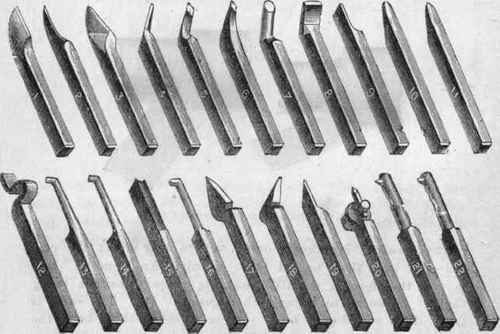
Fig. 15. - Various Slide-rest Tools.
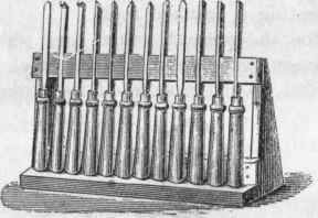
Fig. 16. - Stand for Tools.
Illustrated here (Fig. 16) is a very simple stand for tools which is most useful, as each tool can be seen at a glance. This one is for handled tools for wood.
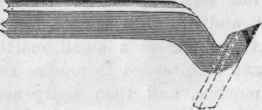
The further consideration of this important subject will be better carried on in connection with cutter bars, especially as these are fast displacing the solid forged tools of which we have been speaking. Those that are cranked are made on the same principle, but are more convenient to grind, and naturally lead up to the cutter bar, as they may be considered as a shank acting as a handle to support a straight bar, ground off at an angle at its upper end (see dotted lines in Fig. 17, representing a cranked tool).
Continue to:
My Books

