Slide-Rest Work In Metal. Part 3
Description
This section is from the book "Turning Lathes", by James Lukin. Also available from Amazon: Turning Lathes: A Guide to Turning, Screw Cutting, Metal Spinning and Ornamental Turning.
Slide-Rest Work In Metal. Part 3
Fig. 17. - Principle of Loose Cutters.
Passing by, for the present, other bars which are made to hold round, square, or oblong section steel, we may go at once to one called, from the name of its inventor, the Haydon
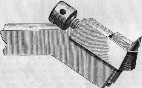
Fig. 18. - Haydon Bar.
Bar. It was designed to carry out to the utmost the principles of double-edged tools. Intended chiefly for square section bars, it will also hold round ones and gouges - the latter being, of course, broken off into short bits about lin. long. Fig. 18 represents this bar, and its construction is evident at a glance. It is sold, accompanied by a full printed description, and with directions for grinding the little cutters. The price varies from 9s. 6d. to 17s. 6d., according to size. The top part, or sling, is a separate piece, and the clamping screw, by drawing it up towards the front end of the bent part of the bar, grips the steel cutter firmly. The latter requires to be ground on three faces - two in front, and one on top. This gives full scope to the workman, in shaping the tool, to meet all requirements. The bar can also, for special purposes, be bent to either side, but it is seldom necessary, as the cutters can be shaped to cut in front or sideways. It is not, however, possible to use such bar for boring and inside work. For this a straight one is used, or an ordinary solid boring tool. In the engraving of the bar we see the top face of the cutter, and one of the two lower ones, the other being precisely similar. In these we have to get, not exactly front clearance (nor does the front line signify), but the clearance of the one face of the tool, which will lie against the shoulder, and of the other, which will be opposite to the cylinder. The meeting of these two with the top face produces, evidently, the two edges which are to remove the shaving. Naturally, we should first grind the front face3, and for this the tool is pushed up, after slackening the screw of the sling, so that the latter may not come into contact with the grindstone. If the shank of the bar is laid on a wooden block resting on the bearers of the grindstone, and the bar is slewed round so as to bring parallel to the stone the face which is to be first ground, a few turns will grind it. The slope, or clearance angle, will be greater or less, according to the height of the block, and the distance the tool has been pushed up in its sling. The thicker the block, or the higher the tool, the greater will be the clearance produced, because the stone will grind more the heel or lower part of the face on which it is engaged. Take Fig. 19, A, to represent the cutter, held up with its two lower faces towards you, and B, the side view which will, of course, show but one face; this will be ground with not much clearance. Then C and D will be similar views, in which the grinding, carried lower down the tool, has produced longer faces - i.e., more clearance. But observe, it is the face, and not the middle line, of which we are speaking : this front clearance we have nothing to do with so far. The slope of it depends on the grinding of the faces, and may be called accidental.
But now it will come into use in quite another way. As yet we have no edges, the shape being like E, if it is a square tool not ground before. Its side view will, in this case, be represented by F. It has, therefore, to be ground off on about the line x, y, until the square end is obliterated. It is now that the front line comes into service, for, in grinding the top face, it will make a given angle with this line, and according to that angle will the sharpness of the two cutting edges be. All this, when it has to be put into words, appears very complicated; but now it has been once explained, it can be summarised in a few words. To grind a cutter: Set the bit of steel up in the sling, to prevent the latter from receiving damage; lay the shank on a block, resting on the bearers of the stone; grind the two lower faces in succession at a tolerably wide angle - 90deg. to 120deg., as a rule, will do. Take out the cutter and turn it round in the sling, so as to bring the face which is left to be ground outwards; lay it on the stone, and grind it to the desired angle with the front line. This is not at all complicated, after all; and when the tiling is being actually done, all will be seen clearly enough. Grinding this third or top face will obliterate the square, as it will bring the face to the line x y of this Figure.
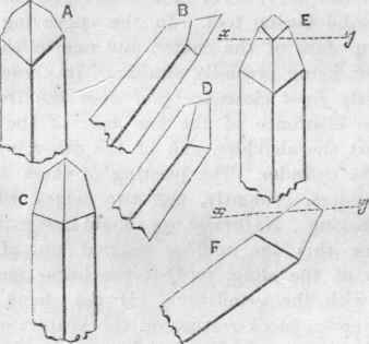
Fig. 19. - Grinding Cutters.
Now here is at once seen the handiness of the cutter bar. There is no forging to be done. The little steel rods, ¼in. to fin., or in large bars fin., square, are readily procured, and can be cut in lengths of an inch or two; and as they are gradually shortened by grinding, they are merely pushed up higher in the sling, so as always to bring the point of the tool to the height of the Lathe centres. After grinding, the steel cutter is not left standing up high, but is pushed down again, so that the point shall never stand above the level of the shank of the tool: if too high, it will have a tendency to chatter; and if it should catch in, it will probably also break.
We may now consider another point connected with the formation of the cutters. It is necessary to know how to obtain the two cutting edges of exactly the angle preferred - say, for instance, 60deg. for wrought iron. Now, this angle depends upon two things conjointly - first, the angle at which the two lower faces meet, called the plan angle of the tool; and then, secondly, upon the angle at which the top face is ground to the front line, formed by the meeting of the aforesaid faces. A graver is a square bar: it has, therefore, a plan angle of 90deg. Grinding off the face at 45deg., with the line formed by the meeting of any two given faces, the edges produced will be 60deg. each, and these are the angles usual with that tool. If we grind the faces of the little cutter, therefore, similarly to make an angle of 90deg., and then grind off the top face at 45deg., we get 60deg. of cutting edge. But an angle of 90deg. gives rather a weak point to the graver or to our cutter, and the latter is preferably ground to a larger angle, the faces meeting at 120deg. The top must be then ground to make 55deg. with the front line, and the result will be two cutting edges of 60deg., as before, but the point of the tool will be strong. The extreme point, even then, is preferably rounded on the oilstone.
Continue to:
My Books

