Clamp And Shelf Fastenings
Description
This section is from the "The Elements Of Wood Ship Construction" book, by W. H. Curtis. Also see Amazon: The Elements Of Wood Ship Construction.
Clamp And Shelf Fastenings
Practice in the method of driving clamp and shelf fastening varies considerable, although the number of fastenings to the frame is rather uniform. For instance, in Fig. 87 there are four fastenings to the frame, two button head bolts driven from the inside and clinched outside, and two driven from the outside and clinched inside. This is a rather unusual fastening. In Fig. 88 there are again four fastenings to the frame, two of them being button headed bolts driven from the inside and clinched outside, and two machine bolts with nuts inside. This is also a rather unusual fastening. In Fig. 89 there are still four fastenings to the frame all of which except one working fastening per frame are headed blunt bolts driven from the outside and clinched inside. The working fastening consists of drift bolts driven through rings inside. In Fig. 90 there are four fastenings to the frame two of which are button-headed bolts driven from the outside and clinched inside and two button headed bolts driven from the inside to within about one inch of the outside of the frame. Note that some of the fastening is omitted in way of the knee. The number of fastenings that may be omitted in way of hanging knees is governed by the amount of knee fastening to be driven. For instance if the lower leg of the knee in Fig. 90 had eight through fastenings, then it would be possible to omit that number of fastenings from the clamps in way of the knee.
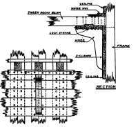
Tween Pecks Shelf And Clamps With Hanging Knees.
Likewise if four of the knee bolts are clinched bolts, then four of the bolts omitted from the clamps may be clinched bolts. Obviously this rule must be applied with some judgment to avoid leaving out too much fastening in in one place and bunching it in another.
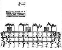
In Fig. 91 all of the bolts fastening the clamps and shelves to the frame are headed blunt bolts driven from the outside. Of course a few of these bolts must be driven from the inside as working fastening but this number is held to a minimum. All of the fastening must be set well in on the outside of the frame to clear the dubbing. Button-headed bolts driven from the outside should be set down in counterbores. Headed drifts, or blunt bolts, may be set in without counterboring.
Clamps, like the ceiling, which will be described later, are generally edge bolted. The customary arrangement is one bolt passing through two and one-half strakes driven in each strake in alternate frame bays, but in many instances bolts of the same length are driven in each frame bay for at least a portion of the length of the ship. Edge scarfs should receive extra edge bolts sufficient to bring the total number of such bolts up to not less than two to the frame bay. Quite frequently more are driven. The same rule for extra edge bolting also applies to scarfs in the shelves.
The fact has already been mentioned that it is desirable to run in the shelf and waterway strakes practically simultaneously. This is principally due to the necessary arrangement of fastening. For instance referring to Fig. 90 it will be seen that it would be advisable to run in the first strake of the shelf and then the waterway, before proceeding with the other strakes of the shelf. When this is done the work can be fastened as it goes along which always makes the better job. Again, referring to Fig. 91 it will be seen that the waterway fastening passes through the shelf and is clinched below. The shelves are also fastened horizontally into the frame, as are also the waterways, although the bolts are not shown in this figure. It will be readily seen that in order to secure the best job the waterways and shelves should be run in at the same time so the fastening each way in each strake can all be driven, thus securing and holding the strake "home".
Arrangement Of Clamps And Shelves Where Hanging Knees Are Not Used.
Miscellaneous
Toward the ends of the vessel the curvature becomes so sharp that it is often impossible to spring the shelf strakes into place and they must therefore be worked out to shape. This is especially true where shelves are carried around elliptical sterns. Very often the shelf strakes are not carried to the extreme ends of the ship. Forward they may be allowed to stop at the collision bulkhead, aft they may be allowed to butt against an inside rim. As a matter of good design, while they may be reduced in size at the ends of the ship, all shelf and clamp strakes should be carried as far forward and aft as possible. Tapering such heavy strakes as the shelves and clamps shown in Fig. 91, as they near the ends of the ship, is not only good practice but serves a very useful purpose. Such strakes if untapered are almost impossible to spring around the luff of the bow in good shape. In the majority of cases they would be split by the band saw before attempting to spring them into place. The latter operation merely converts the timber into two thinner timbers thus making it easier to bend. Tapering serves the same purpose and has the additional advantage of saving some timber and weight.
Ceiling
Heavy scantling ceiling is shown in Fig. 92. Light scantling ceiling is shown in Fig. 93. Since the two figures are the same size and were originally drawn to the same scale, the relative proportions of the ceilings are approximately true and afford a very interesting comparison between the two types of construction.:
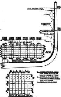
Figure 93. Arrangement Of Ceiling As In One Type Of Light Scantling Vessel.
The operation of ceiling properly begins with the lowermost strake of the heavy, or bilge, ceiling, although as has been previously mentioned, in a vessel having the cross section shown in Fig. 93, where there are no edge bolts in the ceiling, the work may. be started at both the lower edge of the bilge ceiling and at some point between decks. The latter arrangement is the exception to the general rule.
Continue to:
My Books

