Waterways And Decking
Description
This section is from the "The Elements Of Wood Ship Construction" book, by W. H. Curtis. Also see Amazon: The Elements Of Wood Ship Construction.
Waterways And Decking
Main and lower deck waterways with one or two exceptions do not vary greatly in type or arrangement. There may be either two or three strakes. In a two-strake waterway there will be the outer strake and the lock strake. In a three-strake water there will generally be one outer and one inner strake with a lock strake between them, though sometimes the lock strake is placed inboard with the other two strakes outside of it, board face. The calking seam for the inboard face is generally run on the waterway strake.
For the same reasons that outlines of the waterways were shown in connection with clamp and shelf details it has been considered necessary to show outlines of clamp and shelf details in these waterway details. It will be understood that no particular type of clamp or shelf arrangement is confined to use with a given type of waterways.
The width of the outer waterway strake or strakes must be such as to place the lock strake well in on the beam. The depth of the lock on the beam varies from two to three inches depending upon the size of the beam and waterways. The tops of waterways are generally made flush. The strakes are as a rule set square with the upper face of the beam, the outer strake being beveled to fay to the frames or stanchions.
Type 1, Fig. 132 shows a two-strake waterway as it would appear on the weather deck in way of the bulwarks and Fig. 133 shows the same type of waterway as it would appear either on a lower deck or on the weather deck in way of the bridge erection.
The space between the stanchions is chocked flush with the top of the waterways. These chocks should rest on the top timbers as shown in Fig. 132 and are usually fastened in place with hardwood treenails driven as shown. The inboard and outboard faces of these chocks should be exactly flush with the corresponding faces of the stanchions, and a calking seam should be provided at the ends and out.
Figure 132 also shows the proper setting of waterway scarfs. Nibs should be of standard depth and the scarf lengths should be extended beyond the standard if necessary to properly land the nibs. Calking seams must be run on the upper edges of all scarfs.
The most important part of waterway construction is the fastening. These members usually form one of the most important connections of the beams to the side of the ship and it is therefore essential that they be well and carefully fastened.
It will be noted that in this figure the outer strake receives two button-headed bolts driven from the outside and clinched over rings on the inside. The inner, or lock strake receives also two such bolts driven from the outside and clinched over rings on the inside. These four bolts are arranged to square up through the frame or stanchion. In addition two button-headed bolts are driven through both strakes into the chock, in way of the wells, and into the frame in way of the bridge where it is not necessary to fit chocks. For vertical fastening to the beam, each strake has two button-headed bolts driven at each beam, those in the outer strake extending into the clamps, and those in the lock strake being driven into the knee. Scarfs should have not less than two extra bolts between each frame or stanchion.
In Fig. 134 it will be seen that the fitting of shelves makes practically no difference in the number and location of the fastenings but does change the character of some of them. In this figure we have a typical three strake waterway and scarcely any comment need be made except to call attention to the vertical bolting of the lock and inner waterway strakes which, it will be seen, passes through the shelves and is clinched over rings below.
The foregoing descriptions apply to waterways as generally fitted on the main deck or decks below the main deck. When a shelter deck is to be fitted it may or may not be of lighter construction than the main deck. In small vessels it is generally made much lighter while in larger vessels the tendency is to make it even of heavier construction than the main deck. One type of waterway used in shelter decks of light construction is shown in Fig. 135. Here the waterway becomes nothing more or less than a covering board, and is worked and fastened as a covering board. This construction is not often used.
In Fig. 136 we have the waterway as applied to the bridge deck, and here as in Fig. 135 it is practically a covering board, and in fact is generally so called. The construction shown in this figure, including the waterway, clamps, and knee is practically typical for bridge decks, forecastle and poop decks.
On account of being in a location where there is great shrinkage these hanging knees are often fastened with screw bolts instead of the usual clinch bolts.
In either Fig. 135 or Fig. 136, the button-headed bolts fastening the waterway have the heads set down in counter-bores which are plugged in the usual manner.
Figure 137 shows a patented arrangement of steel plates and hanging knees which is being used on a few ships in lieu of waterways and shelves or knees of wood. It is known as a reinforced construction. It may be noted here that this type of construction is used in connection with the diagonal planking system which has been mentioned before. Attention is called to the manner in which the chocks between the frames are dapped or dovetailed in place. These chocks are to receive the end fastening of the diagonal planking.
Figure 138 shows a typical arrangement of heavy scantling waterways and shelves for a shelter-decked vessel having two full decks and a lower tier of beams, known as lower, orlop, or hold beams. Note that the frames extend to the tops of the upper waterways, that the outer strake is dovetailed to the frame, and that the frame heads are covered with a planksheer. The fastening is not shown as there is nothing unusual in its arrangement.
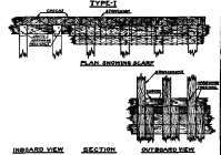
Figure 132. As On Weather Deck In Way Of Bulwark.
Figure 133. As On Weather Deck In Way Of Bridge Also As On Tween Decks.
Waterway Details Also Showing Beam Connections.
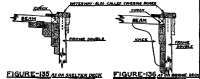
Figure 137. Type-III.
Figure 134. As on Weather Deck In Way of Bulwark.
Miscellaneous Waterway Details Type-I.
Continue to:
My Books

