Waterways And Decking. Part 2
Description
This section is from the "The Elements Of Wood Ship Construction" book, by W. H. Curtis. Also see Amazon: The Elements Of Wood Ship Construction.
Waterways And Decking. Part 2
Where waterways are extended to the stem, or around the stern, the various members have to be worked to shape as shown in Figs. 139 and 140. It will be noticed that not only is it necessary to use a close shift of scarfs at the ends of the vessel, but the scarfs are also shorter than the rule length. The shifts of scarfs that must be used are entirely dependent upon the curvature at the point where the timber is being fitted and the available width of the stock from which the timber is to be cut. Narrow stock will require close shifts of scarfs, and wide stock will permit greater shifts of scarfs, but there is a limit beyond which it is not wise to go even if very wide stock is available. This is due to the fact that where very wide stock is used to secure greater shifts of scarfs the result is often a scarf so cross grained that it has practically no strength. It is also to avoid this condition that scarfs are made shorter than the rule length.
In these figures two strakes of the waterways are shown carried to the stem and around the stern. Where a third waterway strake is fitted it is quite often stopped at the poop and forecastle bulkheads.
The lock strake, where carried around the stern, is made the same depth as the outer strake, that is, the lock is omitted in way of the rim.
The molds for the members to be worked to shape may be prepared in the loft, but should in any case be checked from the ship as some variations are bound to occur.
Where the stern is built up of solid work above the main deck there is no necessity of carrying the waterways around and they are generally allowed to run out against the solid work as shown by the dot and dash lines in Fig. 140.
At the stem in Fig. 139 a natural crook hook is fitted and fastened generally as shown in the figure. This hook has the same depth as the inner waterway strake, and the decking butts against it.
At the stern, where the two members of the inner strake butt at the centerline, an anchor stock is fitted, to avoid the excessive cross grain that would result with an ordinary scarf.
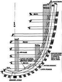
Figure 140. Waterways And Decking At Stern.
Both figures show clearly the chocks between the beams to receive the deck end fastenings and which have been previously mentioned.
The ends of decking should never be run off to a shim end where they land against the waterways, and a nib strake should be provided as shown in the figures. It will be seen that after the angle across the ends of the deck planks becomes rather blunt, the nib strake is either stopped as in Fig. 140 at the stern or merely has the deck plank butted against it as in Fig. 139 at the stem. Very often, however, at the bow the nibbing is carried to the end of the nib strake. There is no fixed rule for the angle across the deck ends at which the nibbing may be left off. However, in the author's opinion, nibs should be cut when the length of the cut across the end of the deck plank exceeds one and one half times the width of the plank.
Standard weather decking is generally square in section as shown in Fig. 141. The standard size is 4 inches by 4 inches, this being the net dimension as the decking is laid. Decking used on decks below the weather deck is often made thinner, and is also frequently made wider than its thickness.
To provide a good wearing surface all decking is invariably finished with vertical or edge grain showing on top face. The lumber from which it is made must be practically perfect.
It is customary to run the calking seam on each side of the deck plank as shown in Fig. 141. This is done at the mill. The total opening of the seam should not as a rule be greater than ⅛ inch nor less than 1/16 inch. General practice seems to favor an opening of about 3/32 inch.
The customary minimum width of nib is shown in Fig. 143 and general arrangements of fastening are shown in Figs. 142 and 144. For the driving of the spikes used in deck fastening, a hole must be bored through the deck plank but not necessarily in the beam. The diameter of this hole is sometimes made the same size as the spike but the better practice seems to be to make it 1/16 inch less, which provides for a slight drift of the spike through the plank. Sometimes when the holes are bored the latter size trouble is experienced by the decking splitting when the fastening is driven. This generally indicates either insufficient wedging of the plank or the use of a spike too large for the size of the decking. If the spike is too large a better job will be obtained by using a smaller spike which will permit the boring of the hole 1/16 inch smaller in diameter than the size of the spike. As before mentioned no hole need be bored in the beam, but the spike must be so set that the chisel point will cut the grain of the wood in the beam.
A common rule for the size of deck spikes is ⅛ inch square and two inches of length for each inch thickness of the deck plank. Thus, the spikes for decking four inches thick would be « inch square and eight inches long. However, spikes of this size will very often give trouble by splitting the decking when they are driven in a 7/16 inch diameter hole. It has also been demonstrated that they are unnecessarily long. Therefore the author commonly uses a spike 1/16 inch less in square size, and one inch less in length than that given by the above rule. That is, the spike for four-inch decking would be 7/16 inch square by seven inches in length and the hole through which it is driven would be ⅜ inch in diameter.
Individual opinions upon these points differ, and as the size of spike to be used in any particular decking is always specified on the plans, it should where possible be used.
Spikes in the decking and similar locations are always set down in counterbores which are fitted with plugs of white pine or other similar wood as shown in Fig. 142. These counterbores are generally bored with special bits called plug bits, which are so constructed that they cut a perfectly clean hole of the exact size required. The depth of the counterbore should be gauged so that after the spike is set down snug there will be from ⅝ to ¾ inch of depth left for the plug. The plugs are then dipped in thick white lead and tapped down against the spike head. They should fit tight in the counterbores.
Figure 141.
Figure 142. Deck Fastening.
Figure 143.
Figure 144. Showing Arrangement Of Fastening.
Miscellaneous Decking Details.
A common rule for the size of plugs is: Two times the diameter of the spike plus ⅛ inch. Thus, the diameter of plug for « inch spikes would be 1⅛ inch, and for a ⅜ inch spikes would be ⅞ inch, etc. Where spikes have extra large heads it may be necessary to add ⅛ inch to the size given by this rule.
Continue to:
My Books

