Model VII. A Letter Rack. Face And Edge Planing, Boeing, And Screwing
Description
This section is from the book "Manual Instruction: Woodwork. The English Sloyd", by S. Barter. Also available from Amazon: Manual Instruction: Woodwork.
Model VII. A Letter Rack. Face And Edge Planing, Boeing, And Screwing
Fig. 156. - The drawing of this model should be made to scale 1/2 , and should include the elevations of back and side, and the projected elevation of one of the sloping fronts (a practical illustration of change of ground line).
Two pieces of some hard, close-grained wood, as sycamore or walnut, are required, one 13 1/2 ins. by 4 ins. by 3/8 in., and one 13 1/2 ins. by 13 1/4 ins. by 3/8 in.
Plane up both faces of each piece true to dimensions, and shoot the edges of the narrow piece for the fronts, down to its width - 3 ins.
The face edge of the wider piece should be planed up true, but as little wood as possible should be removed to attain this. The plan of the back shows the section of the chamfered fillet, which afterwards makes the groundwork on which the shelves are to be screwed.
From the face side, gauge the width of the back, the 1/8 in. for waste between the back and the fillet, and the 1/2 in. for the width of this fillet. Now plane off the back edge of the wood down true to the last made gauged line, and chamfer off the next 1/2 in. with the jack and trying plane to the required angle - 22 1/2°, testing the work with the bevel set at that angle. When the chamfering is correct, saw off the fillet with the panel or tenon saw, and then plane the rough edge true in the shooting board. The edge left rough from the saw cut on the back should now be planed down true to the dimensions - 3 ins., and will now agree with the other piece of wood for the fronts.
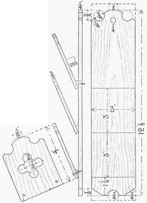
Fig. 156.
Side elevation, with projected front.
Elevation of back.
Plan of back, showing section of chamfered fillet.
Draw on the back the outline of the top and bottom. The circle and semicircles where the boring is to be done need not be made, as if the centre is carefully indicated in its proper place, the bit will create the proper curve as it cuts. Material enough has been allowed for waste at each end, and also in the piece from which the sloping fronts are to be made, as will be seen in the drawing (fig. 157), showing the manner of setting out the fronts. The tops of the fronts are not dimensioned, but they are similar to the top of the back.
To find the centres of the five bored holes which make the design in the middle of each front, draw a faint, short, gauge line, down the middle of each of the pieces, make pencil lines across each, and cutting the gauge lines at the centre of each piece of wood. From these centres the four points which give the other centres of the four holes to be bored can be obtained.
Now bore all the holes in both back and fronts before cutting the latter apart, boring partly from each side in order to avoid breaking the fibres by the pressure. Cut off the fronts, plane the bottom edges true and square, and saw off the corners of both back and fronts a little away from the cut lines. Pare with a chisel back to the lines so as to leave a clean edge.

Fig. 157.
Cut the fillet up into the required lengths - 3 ins., and glue a piece to the bottom of the back of each shelf. While waiting for these joints to dry, clean up the face and opposite sides of the back with a smoothing plane, and finally just touch up the surfaces with glass-paper, to make them dead smooth. Cut lines, to indicate the points where the fronts meet the back, should now be made, and the three fronts can be screwed on when dry, using 5/8 -in. brass-headed screws (trade size, No. 3), as shown in 'side elevation of projected front,' if it is desired to give the finished model a good appearance.
Continue to:
My Books

