Balloon-Frame Construction. General. Description
Description
This section is from the book "A Treatise On Architecture And Building Construction Vol2: Masonry. Carpentry. Joinery", by The Colliery Engineer Co. Also available from Amazon: A Treatise On Architecture And Building Construction.
Balloon-Frame Construction. General. Description
170. Balloon framing, as heretofore explained, is the term given to that system of construction in which the skeleton, or framework, of a building is spiked together with butt joints, and depends almost entirely for its strength and stability upon its exterior covering and the manner in which this covering is applied.
We will now take up the construction of a balloon-frame building, applying, as we proceed, such methods and means as have already been set forth in these pages, and studying, as they appear, such new or additional features as the necessity or the economy of the construction demands.
171. In Fig. 72, A is the stone foundation wall, 1 foot 6 inches in thickness. On top of the foundation wall is spread a bed of lime mortar at c, in which the sill B is laid and well bedded by means of repeated blows from a heavy hammer. When this is done, the outside edge of the sill, which is kept back 1 inch from the face of the wall, is pointed up; that is, the joint between the sill and the top of the wall is carefully scraped off to give it a neat, even finish, and any surplus mortar is removed from the 1-inch projection of wall. The plate is halved and spiked at the corners in the manner described in Art. 82, as shown at a and b, and where the pieces composing it cannot be obtained in sufficient lengths, the sill is pieced out by means of the beveled splice, as shown at d. In exposed situations where high winds are frequent, it is not uncommon to anchor the sill to the wall by means of anchor bolts. These bolts are from 1 inch to \\ inches in diameter, and are firmly built into the mason work of the wall with the thread end projecting above it. Holes are then bored in the sill to fit over these projecting ends, and, after the sill is laid and leveled, it is securely held in place by screwing nuts tight on the ends of the bolts with a washer between each nut and the sill.

Fig
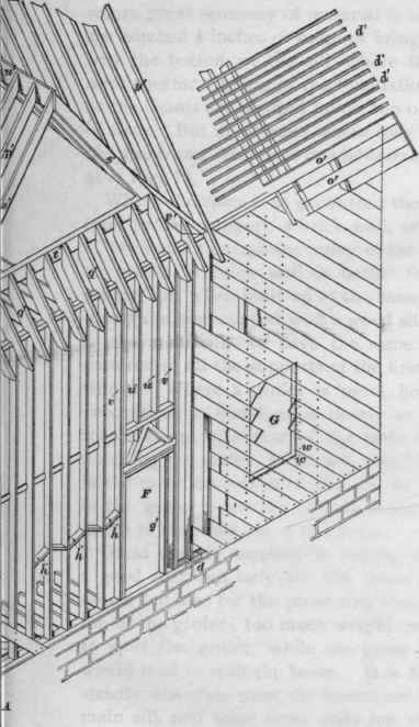
172. After the sill is set in its place, leveled, and its angles squared to be absolutely true, we may proceed to lay the first tier of floorbeams. These are notched over the sill to bring their tops to a level line, as shown in Fig. 30, or, where great economy of material is to be desired, the beams are notched 4 inches or more to bring their under sides flush with the bottom of the sill, where they are bedded in the same mortar topping of the foundation that the sill itself is, or the beams are blocked up on top of the wall with pieces of slate. But in all cases where they are so deeply notched the floorbeams must have a solid bearing on the wall, as shown at e, Fig. 72.
Where the span is so great that the beams must have an intermediate support, a brick wall, or a girder, as shown at C, is carried through the center of the house and is supported on posts. A brick wall is better for the purpose than a girder, for, when built up to the same height as the foundation walls, and capped with a wood sill of the same thickness as the main sill, we have the same amount of shrinkable material in all the supports of the first-story beams and partitions. Where a girder is used, however, we must take precautions to equalize, as nearly as possible, the effect of its shrinkage with that of the main sill. This is done by notching the girder, as shown, and by notching the beams in the same manner as at the sill, so that the solid portion of the girder below the notches is equal in thickness to the depth of the main sill of the house.
Great care is required in cutting these joints to insure a good seat, not only for the beam on the bottom of the notch, but also for the projecting tenon of the beam on the top of the girder; too much weight on the notch would tend to split the girder, while too great a strain on the tenon would tend to split the beam. It is for this reason that in strictly first-class work the beams are simply sized over the main sill, and their inner ends are similarly sized over an interior sill supported on a brick or stone wall.
Whether they meet on a girder or wall, the ends of the beams should be butted together, and held by cleats nailed on each side; they should never be lapped one beam on the side of the other and spiked together, as this produces irregularity in the beam spacing, and makes the subsequent laying of hot-air pipes, etc. very troublesome. The floor-beams having been spaced and securely nailed along sill and girder at the uniform distance of 12 inches or 16 inches on centers, they are then cross-bridged, as shown at f. See Art. 109.
173. While this bridging is in progress, or even before it is commenced, the side walls of the building are started, by setting the corner posts a a' and b b' in position. And after they have been carefully plumbed with a level and straightedge, as shown at D, or preferably by a long plumb-rule and blumb-bob, they are braced in position by two pieces of sheathing nailed securely to the posts and to the sill, as shown at g.
The corner posts are generally composed of two pieces spiked together, as shown at a b', in Fig. 37, and the larger piece is sometimes, though not always, mortised or doweled into the sill.
174. After the corner posts are secured, the studs are spaced along the sill 16 inches on centers and are spiked both to the sill and to the floorbeams; they are then plumbed and carefully alined along the outside edge of the sill, and secured in place with braces similar to those of the corner post, those on the exterior being permanent in the form of sheathing, while the brace extending from the side of the stud to the floorbeam is but a temporary affair, to be removed as soon as the interior partitions and the second-story beams are in place.
These studs and corner posts are all cut to an even length on the ground before they are set in place, and at the same time the notches for the ledger boards k are cut in the studs 4 inches wide and 1 inch deep, and as soon as the studs are set in place, the ledger board itself is fitted and spiked to each stud with two nails.
Continue to:
My Books

