Lintels
Description
This section is from the book "A Treatise On Architecture And Building Construction Vol2: Masonry. Carpentry. Joinery", by The Colliery Engineer Co. Also available from Amazon: A Treatise On Architecture And Building Construction.
Lintels
71. A lintel, often called a cap, is a stone supporting the wall over a door or window opening; and, as it is to resist bending stress, should be a strong, tough stone, having an ample cross-section. The ends of stone lintels should not be built into the walls more than is necessary to give sufficient bearing; 4 to 6 inches at each end is the usual allowance. There should be a little play allowed at each end, so that, if the walls on either side settle unevenly, the lintels can yield slightly without cracking.
72. Strength Of Lintels
Strength Of Lintels. A lintel acts as a beam, and hence the ordinary beam formulas will apply. For uniformly loaded beams, the breaking load is found as follows:
Rule
Multiply twice the breadth in inches by the square of the depth in inches, and also by the proper constant from the table. Divide the product by the span in feet; the quotient will be the breaking weight for a uniformly loaded beam.
Expressed by a formula, this rule is:
2bd2 A
L = W, in which b = breadth in inches; d = depth in inches; L = span in feet; A = constant; W = breaking load in pounds.
If the weight is concentrated at the center, the breaking load is 1/2 W instead of W.
The value of A is, for bluestone, 150; for granite, 100; for limestone, 90; for marble, 120; for slate, 300; for sandstone, 70.
This formula is practically the same as that in Art. 122, Masonry, § 7, the only differences being in the value of the constant A, and in its application to distributed instead of concentrated loads.
73. When the weight on a lintel consists of a dead load, such as masonry, which is not liable to shocks, one-sixth of the breaking load may be taken as safe. If, however, the lintel is subject to live loads of any kind, not more than one-tenth of the breaking load should be taken. In such cases it is better to avoid the use of stone lintels, unless reinforced by angles or beams.
As an example, let it be required to find the breaking load of a bluestone lintel 10 inches wide, 24 inches high, and 7 feet long between supports, and uniformly loaded. Using the formula, 2X10X242X150
W = 7 = 246,857 pounds.
Taking one-sixth of this, gives 41,143 pounds as the safe uniformly distributed load.
74. Relieving Lintels
Relieving Lintels. Often when a long lintel is needed over an opening, the stonework above the lintel is arranged as shown in Fig. 36, in which a is the lintel, and b the stone above it cut with two diagonal joints, as at c. In this way, some of the load is taken off the lintel and transferred to the wall on both sides of the opening.
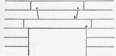
Fig. 36.
If a lintel extends through the wall, and is not supported by angles or beams, the strength may be increased, if the stone is stratified, by cutting it in such manner that the layers will set on edge. Many old Roman and Greek structures show lintels so cut.
75. When considerable weight rests on a stone lintel, a brick relieving arch (see Art. 269, Masonry, § 7) may be used, but, unless much skill is exercised, this detracts from the appearance of the building, if the arch extends through the entire thickness of the wall. To avoid this result, if stone of sufficient depth cannot be used, the lintel may be strengthened by the use of iron beams or angles. When the lintel is of moderate length, it is sufficient to use a piece of angle iron, as shown in Fig. 37, in which a is the stone lintel; b, the angle, which should have its longer side vertical; c, a wooden beam to which the interior woodwork is nailed; d, the brick wall; and e, the window reveal.
76. When the width of the opening is considerable, stone lintels should be supported on I beams. If only the weight of the lintel and wall is to be carried, a single I beam may be used, as shown in Fig. 38, in which a represents the stone lintel; b, the I beam; c, the wooden beam to which the wood finish is attached; d, the reveal; and c, the brick wall.
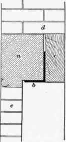
Fig. 37.
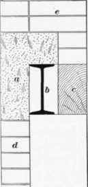
Fig. 38.
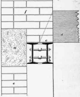
Fig. 39.
When, in addition to the walls, the floorbeams over openings must be carried, it is best to use two I beams, as shown in Fig. 39, in which a is the stone lintel; b, b, the I beams, held together by bolts and separator; c, an iron plate on which the wall rests; d, a floorbeam; e, the window reveal; and f, the brick wall.
When it can be avoided, it is best not to support the weight of a wall upon both stone and steel or wood beams, as the deflection of each material is different, making it practically-impossible for each to carry its proper share of the load. The weight should preferably be borne by the steel beams alone.
Continue to:
My Books

