Ordering Of Material
Description
This section is from the book "Cyclopedia Of Architecture, Carpentry, And Building", by James C. et al. Also available from Amazon: Cyclopedia Of Architecture, Carpentry And Building.
Ordering Of Material
Since the ordering of material is of great importance it will be discussed here somewhat at length. Although this is usually done by men of considerable experience, yet it is advisable that the draftsman should know the method of procedure in order that he may be able to make the detail drawings more advisedly.
Layout. Typical Case. As has been mentioned before, the checker makes details to a large size scale from which he determines the size and amount of material required for certain members. In order to illustrate this, let it be required to determine the size of the plates and the length of the angles used in the cross frame of the plate girder shown on Plate VI. Here the checker first lays off the center to center of the girder to a small scale, say, 3" to 1'. These lines are marked 1 in Fig. 6. He next draws a web to the proper thickness and then follows in turn the flange angles and the bracing angles as indicated by the numbers 2, 3, etc., on the figure. The number of rivets in the top and bottom angle and in the diagonal should be given on the stress sheet. These should be laid off on the "layout," which is the name for the drawing that has just been made, any spacing, preferably 3 inches, being used so that the plate may be kept as small as possible. It is as a usual thing not possible to have the rivet spacing in both the diagonal and the top and the side angles of equal spacing. The number of rivets is usually put in the diagonal at about a 3-inch spacing, and the spacing of the rivets in the top and the side angles is so varied as to fill out the plate as indicated. No rivets should come closer to the edge of the plate than 1 1/2 inches nor further from the edge than 2 inches, and no plate should be less than an even number of inches in width although its length may be in feet, or in inches to an eighth of an inch. It is not policy to place the length of the plate in sixteenths of an inch, since the shopmen are unable to cut that close. Therefore, in determining the size of the plate the rivets should be so placed that a sufficient number should go in and the size of the plate be kept an even number of inches in width. If the rivets alone governed the size of the plate, it would be as indicated by the dotted lines in Fig. 6, and the dimensions would then be as indicated by the dimensions with a line drawn around it. The correct size of the plate is as indicated by the full line.
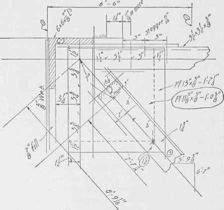
Fig. 6. Layout for Detail in Cross-Frame Connection.
The length of the line from intersection to intersection point is 8'-9 1/16" as indicated upon the drawing. In order to have the length of the diagonal to come out the nearest sixteenth of an inch, the distance of the first rivet from the intersection is taken arbitrarily and is as indicated here, 7 inches. It is not necessary to give this dimension to a thirty-second of an inch, since if the diagonal varies that much from the computed length, it can be drawn up into place by using a drift pin and can be riveted up without injuring the material.
Use by Checker and Draftsmen. The checker has now determined the size of the plate and the length of the diagonal angle and he records them upon the material bill which is to be sent to the mills as an order for material. This layout together with a copy of the material bill should be given to the draftsman when he starts to detail the girder. He will then have the size of a plate and the size of an angle for that particular girder so that the material which has been ordered, probably months before, and has arrived before
Table I. Allowances For Single Lengths
Description of Material or Rule | Allowance Inches | |
Web plates when ends are planed | Add | 5/8 |
Web plates when one end only is planed | ,, | 1/2 |
Web plates over 24" wide, ends not planed | ,, | 3/8 |
Web plates under 24" wide | ,, | 5/8 |
Cover plates and all other plates that must be full length when in work | ,, | 5/8 |
All angles where full length must be maintained | ,, | 5/8 |
All channels when ends are planed | ,, | 5/8 |
All channels when ends are not planed | ,, | 0 |
All I-beams when ends are planed | ,, | 5/8 |
All I-beams when ends are not planed | ,, | 0 |
All Z-bars when ends are planed | ,, | 5/8 |
All Z-bars when ends are not planed | ,, | 0 |
All plates over 7/8" thick (except when ends must be planed) | ,, | 0 |
Order width of all sheared plates 1/4" greater than finished width when planed edges are specified | ||
Order all end connection angles which must be planed or faced 1/16" thicker than specified thickness | ||
Order sole plates planed one side 1/16" thicker than specified | ||
Order sole plates planed both sides 1/8" thicker than specified | ||
Order Tees when ends are not planed | Add | 0 |
the draftsman starts the detail, can be used and will be used in that girder. In case the draftsman details the cross frame without consulting the layouts and bills of material, he is liable to draw up a detail which will demand a plate larger or smaller than that ordered for that particular plate; in the first case a new plate will be required, the ordered plate being placed in the stock pile until some other job comes up in which it can be used; and in the second case the plate ordered will have to be cut down to the size of plate the draftsman has used, thus necessitating extra expense and loss of material.
In accordance with the method above stated, layouts are made, then material ordered for all details, and these layouts and copies of material bills are laid aside to be placed in the hands of the draftsman who detailed the subject. Before the material is ordered from the mills, these bills should of course be checked by another checker or by the squad boss.
In making layouts where angles are placed so that one of their legs is vertical, care should be taken to see that the horizontal leg is at the top in all cases where the angle is exposed to the action of rain and snow. If it is not in this position the angle, in case it is on a slant, will serve as a little trough down which the rain and melted snow will run into the joint at the lower end. In case the angle is not on a slant it forms a pocket-like arrangement so that the snow and ice may lodge upon it to a greater extent than if it had the vertical leg downward. Rust will result and the angle will, therefore, deteriorate. In cases such as lower chords and diagonals of roof trusses, the vertical leg of the angle should extend upward, since here the angles are not exposed to the elements and it is somewhat of an advantage that the angle should catch any dust which falls upon it, and should hold it in order to keep it from dropping to the floor beneath.
Allowances for Planing and Cutting. Single Lengths. When material is ordered it should be so ordered that it will be sure to be of the correct length when it gets to the shop. If the material is ordered in single lengths, that is, the length ordered to go into the finished structure without being cut in two or more pieces after it gets to the shop, it is customary to make some allowance for planing off the ends or for chance errors in the mills where the men may not be careful enough in cutting and may accidentally make the cut a short distance on one side or the other of the mark which would give the exact length The customary allowances for single lengths are given in Table I.
Continue to:
My Books

