Ordering Of Material. Continued
Description
This section is from the book "Cyclopedia Of Architecture, Carpentry, And Building", by James C. et al. Also available from Amazon: Cyclopedia Of Architecture, Carpentry And Building.
Ordering Of Material. Continued
Multiple Lengths. In cases where there are several pieces of the same size and length, they may, for convenience in handling, be ordered in one piece at the mills and cut into lengths after they reach the shop. In this case, however, care must be taken that the multiple length is not too long to ship on an ordinary freight car. The allowances to be made in such cases and the general rules are given in Table II.
Allowances for Pin Material. In case material is ordered for pins, it is necessary that certain allowances be made for turning and for ordering in multiple. The following very general rules are given in Table III.
Table II. Allowances For Multiple Lengths
No. | Rule |
1 | No pieces more than 7 ft. long are to be ordered in multiple lengths unless under special instructions |
2 | In arranging multiple lengths make lengths about 30 ft. and never exceed 32 ft. |
3 | Never order plates over 24" wide in multiple lengths |
4 | Never order plates 7/8" thick in multiple lengths |
5 | Never order channels in multiples unless specially instructed |
6 | Never order I-beams in multiples unless specially instructed |
7 | Never order Z-bars in multiples unless specially instructed |
8 | Plates and shapes to be sheared to length without finishing, add 1" to product of length times number required |
9 | When planed ends are required add specified amount to each piece multiplied and add 1" to multiple lengths so found |
10 | Stiffeners with fillers, add 1/4" to net length of each for planing and 1" to multiple length so found |
11 | Stiffeners when crimped, order same as b-b of girder angles plus 1/4" for planing and add 1" to multiple length so found |
12 | When 4 or less shapes not over 3 ft. long are ordered in multiple lengths, add 5/8" to multiple and add for planing when required. |
13 | When ordering fillers, allow 1/8" clearance at ends when necessary, and add for multiple as for plates |
14 | Make all multiples end with nearest 1/4" |
15 | Tees under 7 ft. long may be ordered in multiple lengths. Add 2" to length times number required and make longest multiple 24 ft. |
16 | If I-beams or channels are cut from long lengths allow loss of 3 1/2" for each cut |
17 | 7"x3 1/2" angles can be multiplied up to and including 3/4" in thickness |
Allowances for Bending. In all cases where angles have to be bent, additional material is required. In such cases the following rules are applicable:
(1) In the case of Fig. 7a. Figure length on c.g. line of angles and add 1" for each bend when the angle of bend is not more than about 30°; add 2" for each bend when the angle is between 30° and 60°; over 60° ask for special instructions from the forge shop.
(2) In the case of Figs. 7b and 7c. In the case of sharply curved end angles or when sharp bends are made near ends, add to the length figured on the c.g. line as follows: 3-inch angles add 4"; 4-inch angles add 5"; 5-inch angles add 6"; 6-inch angles add 7"; 7-inch angles add 8"; and 8-inch angles add 9".

THE CHICAGO CITY HALL UNDER CONSTRUCTION Courtesy National Fireproofing Co.
Table III. Allowances For Pin Material
No. | Rule |
1 | Pins up to and including 4" in diameter, add 1/8" to finished diameter for turning |
2 | Pins 4" to 6" in diameter, add \" to finished diameter for turning |
3 | Pins over 6" in diameter, add \" to finished diameter and order them rough turned unless specially instructed to the contrary |
4 | Pins up to and including 6" in diameter shall be ordered in multiple length of about 12 ft. Add 7/16" for each tool cut and 1" to multiple length thus found |
5 | Pins over 6" in diameter shall be ordered in single pieces and to exact length required |
6 | When pins are over 4" diameter, ordered diameters must end in no fractions smaller than quarter inches |

Fig. 7. Illustration Showing Angle Bends.
Shop Bills. In order to facilitate the getting out of certain articles which are of the same general form but of different dimensions, and for convenience in tabulating information relative to certain material either before or after it has been assembled into members for structures, certain bills called "shop" bills are used. These bills, which save much drafting and much letter writing, may be of almost any character to suit the practice of the plant. Figs. 8 to 26 give the headings of various bills and Fig. 27 gives the heading of a bill which is used in case it becomes desirable to change an order which has been sent in. The lower part of Fig. 27 is suitable for all of the other bills.
These bills are made on thin paper so that prints may be made from them and sent to the various shops concerned. A copy of each should also be filed in the engineer's office, and all bills of each job should be kept together by binding in some way.
ORDER NO.. .......... --------------------------------------------- ------------------------------------ | Saline Bridge Company --------------------------- -BRANCH | Sheet no. . -------------- ---------------------------- ---------------------------- | ||||||||||||
Cast Filling Rings |
Steel Filling Rings |
| ||||||||||||
MARK | NO. OF PCS. | DIAM. | DIAM. | WIDTH | MARK | NO, OF PCS. | DIAM | WIDTH | THICK | MATERL RECfD | MARK | NO. OF PCS. | INSIDE DIAM. | WIDTH |
D | H | w | D | w | T | D | w | |||||||
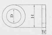
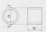
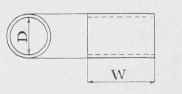
Fig. 8. Shop Bill for Standard Filling Rings
Order no......... ............... .............. | Saline Bridge Company BRANCH | Sheet No.. . . ................... ........................... | ||||||||
Sleeve Nuts |
Turn Buckles | |||||||||
MARK | NO. OF PIECES | DIAM. SCREW | LENGTH | REMARKS | MARK | NO.OF PIECES | DIAM. SCREW | LENGTH | LENGTH | MARK |
U | L | U | X | L | ||||||
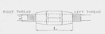
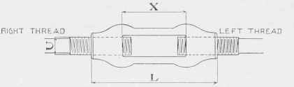
Fig. 9. Shop Bill for Sleeve Nuts and Turn Buckles
Order No........ .............. .............. | Saline Bridge Company ............................BRANCH | Sheet No............ ............... .............. | |||||
Clevises For | |||||||
MARK | NO. OF PIECES | DlAM. | SCREW | PIN | GRIP | REMARKS | |
D | U | P | G | ||||

Fig. 10. Shop Bill for Clevises
Order No. ........... .................... .................... | Saline Bridge Company .................... BRANCH | 5heet No. .......... .................... .................... | ||||||||
Cotter Pins and Cotters For | ||||||||||
mark | NO. PCS. | DIAM. of pin | GRIP | HEAD | COTTER | LENGTH OF PIN | ||||
DIAM. | thick's | LENGTH | DIAM. | UNDER HEAD | OVERALL | REMARKS | ||||
P | H | T | c | D | L | M | ||||
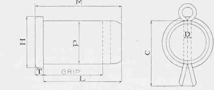
Fig. 11. Shop Bill for Cotters and Cotter Pins
Order No........... .......... .......... | Saline Bridge Company ....................BRANCH | Sheet No. .......... .................... .................... | |||||||||
Pins and Lomas Nuts | |||||||||||
MARK | NO . PCS. | DIAM. | GRIP | SCREW | NUT | LENGTH OVER ALL | NO. PILOT NUTS | NO. DRIVING NUTS | REMARKS | ||
DIAM. | LENGTH | DIAM. | THICKNESS | ||||||||
P | G | D | T | S | N | L | |||||

Fig. 12. Shop Bill for Pins and Lomas Nuts
Order No........... .................... .................... | Saline Bridge Company BRANCH | Sheet No........... .................... .................... | |||||||
Upset Screw Rods For | |||||||||
MARK | NO.REQ'D | SIZE OF ROD | LENGTH OVER-ALL | UPSET | REMARKS | ||||
REG. RODS | TEST RODS | DIAM. | LENGTH | ADD FOR ONE UPSET | MATERIAL REQ'D | ||||
L | U | M | |||||||

Fig. 13. Shop Bill for Upset Screw Rods
SheetNo.... ........... .......... |
Clevis Rods For | Made By 19 | Checked By...........19 | In Charge, of. | |||||||||||||||||
Saline Bridge Company BRANCH | MARK | NO. REQ'D | LENGTH C.TOC PINS | SIZE | LENGTH OVER-ALL | ROD | -MATERIA REQ'D | LEFT CLEVIS RIGHT CLEVIS | REMARKS | ||||||||||||
REG. RODS | TEST R0D5 | UP5ET | DIAM | PIN | GRIP | DIAM | PIN | GRIP | |||||||||||||
DIAM. | LENGTH | ADOFOR ONE UPSET | |||||||||||||||||||
L | U | M | D | P | G | D | P | G | |||||||||||||
Material. | Specif.__________ | PAINT _ _ ----------------------- | |||||||||||||||||||
ORDER NO..... | |||||||||||||||||||||
• | |||||||||||||||||||||
Finished Surfaces in Pinholes are Coated with White Lead and Tallow Before Shipment | |||||||||||||||||||||
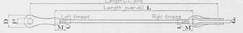
Fig. 14. Shop Bill for Clevis Rods
Sheet No...... ........... ........... |
Loop Rods For | Made By..... 19 | Checked 3y.....19.. | InCharge oF........ | |||||||||||||||||||||||
Saline Bridge Company | |||||||||||||||||||||||||||
MARK | MO. REQ'D | SIZE OF ROD | LENGTH CtoCof PIN5 | LONG END | SHORT END | Material.Wrought Iron | Specif: . _ | INSPECTION-- ...... | |||||||||||||||||||
REG rod: | test RODS | LOOP | UPSET | LENGTH CtO END | MATERL REQ'D | LOOP | UPSET | LENGTH Cto END | mater'l REQ'D | ||||||||||||||||||
PIN | FLAT | TEN | ADD | DIAM | LENGTH | ADD | PIN | FLA1 | TEN | ADD | DIAM | LENGTH | ADD | ||||||||||||||
c | P | E | F | U | M | L | P | E | FI | U | M | LI | |||||||||||||||
Order No______ | |||||||||||||||||||||||||||
Finished Surfaces in PiN Holes Are Coated With White lead and Tallow Before Shipment | |||||||||||||||||||||||||||

Fig. .15. Shop Bill for Loop Rods
Sheet No..... .......... ....... |
Adjustable Eve Bars For | Made By. 19.... | Checked By....19.... | In Charge of...... | ||||||||||||||||||||||||||
Saline Bridge Company ............BRANCH | ||||||||||||||||||||||||||||||
MARK | NO.REQ'D | LENGTH CtoC PINS | LONG END | SHORT END | Material_______ | SPECIF.,......... | Paint... ......... | |||||||||||||||||||||||
REG BARS | TEST BARS | BAR | HEAD D | UPSET | LENGTH C TO END | mater'l req'd | BAR | HEAD D | UP5ET | LENGTH CTOEND | mater'l REQ'D | |||||||||||||||||||
WlDTH | THICK | PIN | DIAM | THICK | ADD | DIAM | LENGTH | ADD | WlDTH | THICK | ADD | DIAM | LENGTH | ADD | ||||||||||||||||
c | D | D | T | U | M | L | P | D | T | U | M | L | ||||||||||||||||||
Order No.. | ||||||||||||||||||||||||||||||
PIN H0LE5 BORED....... | ||||||||||||||||||||||||||||||
Finished Surfaces in Pin Holes Are Coated With White Lead and Tallow Before Shipment. | ||||||||||||||||||||||||||||||

Fig. 16. Shop Bill for Adjustable Eye Bars
Order No............ ........................ ........................ | Saline Bridge Company BRANCH | Sheet No............. ........................ ........................ | ||||||||||||
Eve Bars For | ||||||||||||||
MARK | NO. REQ'D | SIZE | LENGTH | HEAD D | HEAD Dl | MATERIAL REQUIRED | ||||||||
REG. BARS | TEST BARS | WIDTH | THICK | CtoCof pin's | PIN | DIAM. | THICK | ADD | PIN | DIAM. | THICK | ADD | ||
C | P | D | T | Pl | Dl | Tl | ||||||||
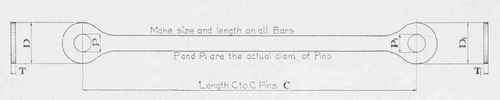
Fig. 17. Shop Bill for Ordinary Eye Bars
Saline Bridge Company | |||||||||||||||||||
OrderNo. ......... | ............BRANCH | Sheet No. ......... ......... ......... ......... ......... | |||||||||||||||||
| |||||||||||||||||||
|
|
|
|
| A 1 3 | ||||||||||||||
Bolt A | Bolt B | LAG SCREW C | Bolt D | Bolt E | Bolt F | ||||||||||||||
No. REQ'D | GRIP | LENGTH | no. REQ'D | GRIP | LENGTH | MATR'L req'd | NO. REQ'D | LENGTH | No. req'd | GRIP | LENGTH | MATRl REQ'D | No. REQ'D | GRIP | LENGTH | MATRL req'd | NO. REQ'D | GRIP | LENGTH |
6 | L | G | l_ | L | G | L | G | L | G | L | |||||||||

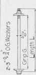
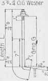


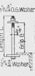
Fig. 18. Shop Bill for Floor Bolts
Saline Bridge Company | |||||||||
Order No....... ............. ........... | ............. BRANCH | Sheet No ......... ............... ............ | |||||||
Turned Bolts For | |||||||||
mark | no. of PC5 | DIAM. OF BOLT | LENGTH | SCREW | LENGTH OF BOLT | WAS DIAM. | THICK | REMARKS | |
LENGTH | DIAM | ||||||||
D | B | M | U | L | W | T | |||

Fig. 19. Shop Bill for Turned Bolts
OrderNo ......... ........... | Saline Bridge Company ... BRANCH | Sheet No ......... .............. .............. | |||||||||||||||||||
| |||||||||||||||||||||
ANCHOR NO. 1 | ANCHOR NO. 2 | ANCHOR NO.3 | HACKED BOLT | SPLIT BOLT | EXPANSION BOLT | ||||||||||||||||
NO. OF PCS. | DIAM. | DIST. | LENGTH OF mat'l | MO. OF ANG'S | SIZE OF ANGLES | LENGTH OF ANGLES | NO. OF ANCH. | DIST. | LENGTH OF FLAT | NO. OF PCS | DIAM. | LENGTH | SIZE OF | NO. OF PCS. | DIAM. | LENGTH | SIZE OF WASHER | ISO. OF PCS. | DIAM. | LENGTH | THICK OF METAL |
A | B | WASHER | |||||||||||||||||||

Fig. 20. Shop Bill for Anchors and Anchor Bolts
Order Assigned to Columbus ...... Plant | Saline Bridge Company shop bill | work Fabricated at Columbus...... plant | |||||||||||||||||
Name of Structure Bridqe over Branch of. Teh Mile Creek | |||||||||||||||||||
Name of CUSTOMER.. Nelson and Buchanan Co., (ord.427) | |||||||||||||||||||
NO. OF PIECES | DESCRIPTION | LENGTH | PIECE MARK | CALC WT. ONE PIECE TOTAL | REMARKS | ORDERED | |||||||||||||
NO. Of PIECES | SECTION | PER FT IN LBS. | LENGTH | ITEM NUMBER | |||||||||||||||
FEET | Inches | FEET | inches | ||||||||||||||||
4 | F | ||||||||||||||||||
4 | /- beams | 15 | 9 1/4 | 15" | 42 | 15 | 9 1/4 | ||||||||||||
32 | Lug Ls | 0 | 7 1/2 | 3x2 1/2x 1/2 | |||||||||||||||
16 | ,, | 0 | 5 | ,, | |||||||||||||||
16 | End Conn. Ls | 0 | 10 | 4 x 3 x 8 | |||||||||||||||
2 | End 5rrut5 | 5 | |||||||||||||||||
2 | Channels | 18 | 0 | 6" | 8 | 18 | 0 | ||||||||||||
36 | Bearing Pls. | 0 | 5 | 3x1/2 | |||||||||||||||
Fig. 21. Shop Bill for Members of Bridge
Order Assigned to Columbus Plant | Saline Bridge Company | Work Fabricated at Columbus Plant | |||||
Name of Structure Neff Bridge on Cline Free Pike | |||||||
Name of Purchaser. .. Huston . and_ Cleveland | |||||||
Erector's List of Field Rivets and Bolts. | |||||||
NUMBER REOUIRED | DISCRIPTION | DIAM. | GRIP | length | SHAPE OF HEAD | PIECES CONNECTED AND REMARKS | |
52 | Bolts | 5/8 | 5/8 | 1 1/2 |
| Buckle Pls and P2 to Girders GIR & L | |
8 | ,, | ,, | 1 5/8 | 1 3/4 | ,, | ,, ,, ,, ,, ,, ,, ,, ,, ,, | |
I92 | ,, | ,, | 3/4 | 1 1/2 | ,, | " " " " " Stringers SI & S2 | |
64 | ,, | ,, | 1 1/16 | 2 | ,, | ,, ,, ,, ,, ,, ,, ,, ,, ,, | |
50 | ,, | ,, | 5/8 | 1 1/2 | ,, | to PLs P2 | |
2 | ,, | 1/2 | 7/8 | 1 1/2 | ,, | Name Plate to GIR | |
4 | Rivets | 5/8 | 11/16 | 2 1/2 |
| B2 to S2 | |
2 | ,, | ,, | 1/2 | 1 7/8 | ,, | B2 to GIR & L | |
4 | ,, | ,, | 1/2 | 1 7/8 | ,, | B2 to BL | |
8 | ,, | ,, | 1/2 | 1 7/8 | ,, | Bl to Railinq on GIR & L | |
Fig. 22. Erector's List of Field Rivets and Bolts
Order No.......... .................... .................... | Saline Bridge Company ..............................-BRANCH | Sheet No.......... .................... .................... | ||||||||||
Rivets and Bolts For | ||||||||||||
RIVETS (PLAIN) | RlVETS (COUNTERSUNK) | BOLTS | ||||||||||
NUMBER REQUIRED | DIAM. | LENGTH UNDER HEAD | REMARKS | NUMBER REQUIRED | DIAM. | LENGTH OVER ALL | REMARKS | NUMBER REQUIRED | DIAM. | LENGTH UNDER HEAD | SHAPE OF HEAD | REMARKS |
Fig. 23. Shop Bill for Field Rivets and Bolts
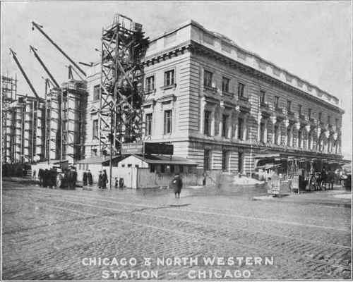
CONSTRUCTION OF THE CHICAGO AND NORTHWESTERN PASSENGER STATION AT CHICAGO.
Courtesy National Fireproofing Co.
Order Assigned to _________________Plait | SHIPPING BILL (RIVETED WORK) | Work Fabricated at .............Plant | ||||||||||||||||||||||
Name; of Structure . ........................................ | ||||||||||||||||||||||||
Name of Purchaser ......................................... | ||||||||||||||||||||||||
Ship to.................................................. | ||||||||||||||||||||||||
ShipVia. ................................................ | ||||||||||||||||||||||||
MEMBER | MATERIAL | SHIPMENT | ||||||||||||||||||||||
no. REQD | NAME | MARK | SHEET MO. | DESCRIPTION | LENGTH | CALC. WT. ONE PIECE TOTAL | NO'.' PIECES | REMARKS | WEIGHT' " | |||||||||||||||
FEET | INCHES | |||||||||||||||||||||||
- | - | |||||||||||||||||||||||
1. | * | |||||||||||||||||||||||
-. | ||||||||||||||||||||||||
' | ||||||||||||||||||||||||
Fig. 24. Shipping Bill
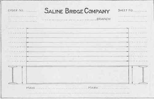
Fig. 25. Shop Bill for I-Beams.
ORDER ASSIGNED TO Saline Bridge Company work Fabricated at
......_______...Plant _____________...Plant name of Structure_____________________________________________________..._ name of Purchaser_______..__________________________________________________
Fig. 26. Shop Bill with Blank Space for Sketch ]
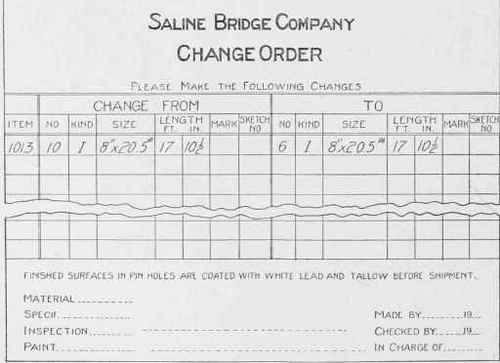
Fig. 27. Sheet Used for Change of Order.
Continue to:
My Books

