Practical Miter Cutting. Part 8
Description
This section is from the book "Cyclopedia Of Architecture, Carpentry, And Building", by James C. et al. Also available from Amazon: Cyclopedia Of Architecture, Carpentry And Building.
Practical Miter Cutting. Part 8
In Fig. 319 are shown a plan and elevation of a moulding which has more projection on the front than on the side. In other words, A B represents the plan of a brick pier, around which a cornice is to be constructed. The projection of the given profile is equal to C, the profile in elevation being shown by C1. The projection of the front in plan is also equal to C, as shown by C2. The projection of the left side of the cornice should be only as much as is shown by D in plan. This requires a change of profile through D, as shown by D. To obtain this true profile and the various patterns, proceed as shown in Fig. 320, in which A B C D represents the plan view of the wall, against which, in its proper position, the profile E is placed and divided into equal spaces, as shown by the figures 1 to 12. Through 1 2, parallel to C D, draw G F. Locate at pleasure the projection of the return mould, as B H, and draw H G parallel to B C, intersecting F G at G. Draw the miter-line in plan, G C. From the various divisions in the profile E, draw lines parallel to C D, intersecting the miter-line C G as shown. From these intersections, erect vertical lines indefinitely, as shown. Parallel to these lines erect the line K J, upon which place a duplicate of the profile E, with the various divisions on same, as shown by E1. Through these divisions draw horizontal lines in-
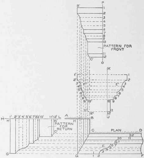
Fig. 320.

FRONT AND REAR VIEWS 0F RESIDENCE 0F HBNRY STEINBRENNER, BELLFLOWER AVENUE, CLEVELAND, OHIO.
Watterson & Schbeider, Architects, Cleveland, Ohio tersecting the smilarly numbered vertical lines, as shown by the intersections Gto 12'. Trace a line through these points. Then will F1 be the true section or profile on H B in plan.
Brick Used on Exterior is McCausland Brick, Made at Akron, Ohio.
Roofs Covered with "Imperial" Red Tile.
For the pattern for the return H G C B in plan, extend the line
A B, as B M, upon which place the stretchout of the profile F1, being careful to measure each space separately (as they are unequal), as shown by figures 1' to 12' on M B.
At right angles to this line and through the figures, draw lines which intersect by lines drawn at right angles to H G from similar points on C G. Trace a line through the points thus obtained. Then will H1 G1 C1 B1 be the pattern for the return mould.
The pattern for the face mould C G D F is obtained by taking a stretchout of the profile E and placing it on the vertical line P O, as shown by similar figures, through which, at right angles to P O, draw lines intersecting similarly numbered lines previously extended from C G in plan. Trace a line through these intersections. Then will 1 B1 C1 12 be the miter pattern for the face mould.

Fig. 322.

Fig. 321.
In Fig. 321 is shown a perpesctive view of a gore piece A joined to a chamier. This presents a problem often arising in ornamental sheet-metal work, the development of which is given in Fig. 322. Let A B C D show the elevation of the corner on which a gore piece is required. H 7' E in plan is a section through C D, and E F G H is a section through X I, all projected from the elevation as shown. The profile 1 7 can be drawn at pleasure, and at once becomes the pattern for the sides. Now divide the profile 1 7 into an equal number of spaces as shown, from which drop vertical lines onto the side 7' E in plan, as shown from 1' to 7'. From these points draw lines parallel to F G, intersecting the opposite side and crossing the line 7' \" (which is drawn at right angles to F G from 7') at 1" 2" 3" 4" 5" 6". Draw any line parallel to C D, as K J, upon which place all the intersections contained on 7' 1" in plan, as shown by 1° to 7° on K J. From these points erect perpendicular lines, which intersect by lines drawn from similarly numbered points in elevation parallel to C D. Through the points thus obtained trace a line. Then will lv to 7v be the true profile on 7' \" in plan. For the pattern for the gore, draw any vertical line, as A B in Fig. 323, upon which place the stretchout of the profile lv 7v in Fig. 322, as shown by similar figures on A B in Fig. 323. At right angles to AB, and through the figures, draw lines as shown, Now, measuring in each instance from the line 7' 1" in plan in Fig. 322, take the various distances to points 1' to 7', and place them in Fig. 323 on similarly numbered lines, measuring in each instance from the line A B, thus locating the points shown. Trace a line through the points thus obtained. Then will F G 7 be the pattern for the gore shown in plan in Fig. 322 by F G 7'.
In Fig. 324 is shown a face view of a six-pointed star, which often arises in cornice work. No matter how many points the star has, the principles which are explained for its development are applicable to any size or shape. Triangulation is employed in this problem, as shown in Fig. 325. First draw the half-outline of the star, as shown by A B C D E F G. Above and parallel to the line AG, draw JH of similar length, as shown. Draw the «ection of the star on A G in plan, as shown by J K H. Project K into plan as shown at I, and draw the miter-line B I, C I, D I, E I, and F I. As K H is the true length on I G, it is necessary that we find the true length on I F. Using I F as radius and I as center, draw an arc intersecting I G at a. From a erect a line cutting J H in section at b. Draw a line from b to K, which is the true length on I F.
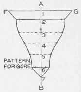
Fig. 323.

Fie. 324.
For the pattern, proceed as shown in Fig. 326. Draw any line, as K H, equal in length to K H in Fig. 325. Then, using K b as radius and K in Fig. 326 as center, describe the arc b b, which intersect at a and a by an arc G G struck from H as center and with F G in plan in Fig. 325 as radius. Draw lines in Fig. 326 from K to a to H to a to K, which will be the pattern for one of the points of the star of which 6 arc required.
Continue to:
My Books

