Counterbores With Inserted Pilots
Description
This section is from the book "Modern Shop Practice", by Howard Monroe Raymond. Also available from Amazon: Modern Shop Practice.
Counterbores With Inserted Pilots
These are useful when the counterbores need frequent sharpening, or when holes of a variety of sizes are to be counterbored to the same size. A common form of counterbore having an inserted pilot is shown in Fig. 155.
Drilling And Turning To Size
When making this counterbore, the stock should have a roughing chip taken off, and the hole E drilled part way from the shank end. This drilling may be done in the speed lathe, the drill being held in a chuck in the head spindle; the center in the opposite end of the piece should be on the dead center of the lathe. If the piece is turned a one-half revolution occasionally, the drill will cut accurately enough, as perfect alignment is not necessary in this hole, since it is intended only for use when driving out the pilot.
Fig. 155. Counterbore with Inserted Pilot.
After drilling, the shank end should be carefully countersunk. The piece is now ready to be turned to grinding size, which should be from .015 to .020 inch oversize. After the outside has been turned, the hole for the pilot is drilled and bored, the large end of the counter-bore running in the steady rest.
Cutting Edges
The coun-terbore should have four cutting edges for all ordinary work; these may be made with a side milling cutter the face of which is sufficiently wide to cover the width of tooth. The form of cutter is shown in Fig. 156, while an end view of the teeth of the coun-terbore is shown in Fig. 157. When milling the teeth, the counterbore can best be held in the chuck on the spiral head. If a more stubbed form of tooth is needed than the one shown in Fig. 155, the spiral head may be tipped to the desired angle and the cutter fed through the counterbore, instead of sunk into it.
Fig. 156. Special Milling Cutter for Counterbores.
Courtesy of Becker Milling Machine Company, Hyde Park. Massachusells.
Hardening
After milling, the burrs should be removed, and the counterbore stamped and hardened. To harden, it should be heated to a red nearly the whole length of body; when dipped in the bath, it should be inverted in order that the teeth may be uppermost; it should be worked up and down rapidly in the bath until the red has entirely disappeared, and allowed to remain until cold. If the counterbore is larger than 1 inch in diameter, the strain must be removed immediately after removing from the bath by heating the piece over the fire, as already explained.
The pilot should be turned, as shown in Fig. 158. A and BB should be left about .010 inch large for grinding after hardening; C should be turned 1/32 inch smaller than the hole in the mill, as this does not bear when the pilot is in place. A slight depression should be made between the head and the first bearing point B for the emery wheel to pass over in grinding. A is the only part that needs to be hard, but, unless a piece of tube is slipped over the stem B when the pilot is put in the bath, it will be almost impossible to harden A the entire length and leave B soft. As A is likely to rough up when used, it is best to harden a short distance on the stem B, unless there should be a great difference in size between A and B. In the latter case a tube, or a piece of iron with a hole drilled in the end the size of B and having the end beveled, as shown in Fig. 159, should be slipped over B when the pilot is heated. The cover should be slipped over the stem and up against the shoulder of the head to prevent a water line; if this precaution is taken, there is no danger of the pilot cracking under the head.
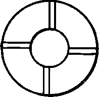
Fig. 157. End View of Teeth of Counterbore.
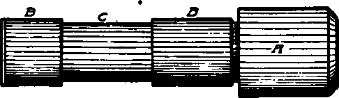
Fig. 158. Pilot for Counterbore.
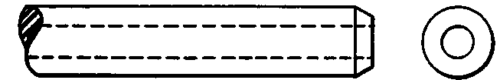
Fig. 159. Cover for Pilot When Hardening.
Grinding
After hardening and tempering, the pilot is ground to size at A, and the portions BB are ground to fit the hole of the counterbore. After grinding, the pilot is forced into place. The counterbore may be ground with the pilot in position. When the counterbore is dull the pilot should be forced out of it, and the cutting edges ground with an emery wheel.
Counterfoores With Single-Edged Adjustable Cutter
A very satisfactory form of adjustable counterbore that works well where a tool with but one cutting edge is needed, is shown in Fig. 160. This tool has a rather wide range of adjustment, and can be made at a nominal cost. The cutter A may be made from carbon tool steel or highspeed steel, according to the use to which it is to be put; it is placed at an angle of 45 degrees with the shank axis. The cutter is adjustable to position and locked by the knurled nuts DD and bound by the set screw C. The pilot E may be used in holes of various sizes by providing sleeves the holes of which fit the pilot and the diameters of which fit the holes to receive them. The shank B may be straight or tapering according to the custom in the individual shop.
This form of counterbore is sometimes provided with a rectangular-shaped cutter instead of the round one shown. When this is desirable, the rectangular-shaped hole to receive it may be produced with a fishtail cutter, described on page 108. In the case of the counterbore under consideration, however, it would be necessary to turn the swivel table of the milling machine to give the desired angle.
Fig. 160. Single-Edred Adjustable Counterbore.
The fishtail cutter will produce a hole with rounded ends. If this is objectionable, the ends may be filed square or may be squared with a broach. For the general run of work, however, the rounded ends are not objectionable. In fact, for the majority of jobs a round cutter in a round hole, as shown in the cut, would answer as well as one made rectangular in form, and could be made for a fraction of the cost.
Continue to:
My Books

