Patterns From Drawings
Description
This section is from the book "Modern Shop Practice", by Howard Monroe Raymond. Also available from Amazon: Modern Shop Practice.
Patterns From Drawings
As already explained, the pattern maker must understand working drawings in order to construct patterns from them directly. These drawings are usually made to a scale much less than the actual size of the required work, and always represent the completed or finished machine or one of its parts.
Drawings are made for the machine shop to guide the machinist in cutting, turning, planing, and fitting the parts given, so as to produce in the castings the shapes, sizes, and general requirements of the articles to be constructed. Hence there is less liability for mistakes after the castings reach the machinist, as he has before him not only the drawing with its accurate dimensions to work from, but also the castings for the machine or its parts, from all of which the construction and uses of these several parts can easily be understood.
On the other hand, the pattern maker, with the aid of the same drawing, must imagine the casting before him, and must build something in wood which will produce that casting in metal. This pattern, in some cases, will be a duplicate of the required casting, but more often it has only a general resemblance to it, with core prints attached, and is external only, with nothing to show the internal openings, chambers, and winding passages that must be provided for by "coring." The core boxes, in which the cores are to be formed, are not shown in the drawings furnished to the pattern maker, but most be provided by him in correct shapes and sizes, in addition to the pattern itself with its added core prints. In building a pattern the workman, as before stated, must allow for shrinkage. He must also allow for draft and for finish. Shrinkage. The shrinkage of cast iron when cooling in the moulds is, as has before been stated, about 1/8 inch to each foot, and the manner of obtaining the exact sizes for different parts of the pattern has been explained under the head of " Rules" (page 38). For brass or bronze castings a greater allowance must be made, averaging 3/16 inch to each 12 inches. Shrinkage rules for brass (3/16 inch to the foot) can be obtained, and must be used for all patterns made from brass.
Draft
After shrinkage, the second point of importance in a well-made pattern is draft. By this term is meant the bevel or taper made on all vertical parts of the pattern so that it can easily be lifted from the sand without injury to the mould. This is best illustrated as in Fig. 134, in which it will be seen that 'f the diameter of a pattern at a wore to be the same as that at b, the latter point would drag over the whole length of the Baud until it reached the former point. As the sand is held together only very lightly, this dragging would be likely to dislodge some of the particles and make it necessary to mend the mould. In order to avoid this, the diameter at a is made slightly greater than at b, so that the body of the gland is tapering, and the moment it is started out the whole surface from a to b is clear of the sand and can be removed without injury thereto. This difference in the diameters at a and b is called the draft of a pattern. The amount of draft depends upon the length of the port that is to be drawn out of the sand.

Fig. 134.
The allowance for draft varies with the pattern, and is often r or less on different parts of the same pattern. For example, ift on the outside of the pattern of a pulley rim 24 inches in (er and 6 inches face, should be 1/8 inch to the foot, while on side of the rim and on the hub of the pully it should be in the f 3/8 inch to the foot. The reason for this difference is that of the rim is often turned and finished straight, and for ason the least possible amount of draft that will allow of the being removed from the sand should be used; while on the of the rim a greater amount of draft strengthens the rim, which must sustain the strain and pressure of the belt. In general the draft should be from 1/8 inch to § inch for each 12 inches, the latter amount in all cases where the. removal of the metal thus added will not greatly increase the expense of working the casting. To obtain any required amount of draft correctly, a draft template, kept with other tools and templates, will be found convenient and useful, saving much time when changing from one ratio of draft or bevel to another. It is made as follows:
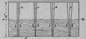
Fig. 135.
Take any straight-grained board 14 inches to 16 inches long and 12½ inches wide, as shown in Fig. 135. Having jointed the edge a perfectly straight, draw the line b perpendicular to the edge and 12 inches long, using a square and a sharp-pointed knife (not a scratch-awl or a lead pencil). On the edge a carefully measure ¼ inch on each side of b; and at the upper extremity, with the same care, measure 3/8 inch on each side of b; connect the last two points thus found with the first two on the edge a, by a sharp knife line, and the result will be a right and left slanting line, having, with reference to the perpendicular, a slant of 1/8 inch to a foot. These lines should each be marked "1/8 inch," as shown in the drawing.
Now draw a second perpendicular c, at a distance of 1½ inches or 2 inches from the first. On the edge of the board a, again carefully mark off ¼ inch on each side; at the other extreme mark off 7/16 inch on each side of c, and again connect the latter points with the former. The result will be a taper of 3/16 inch to a foot. Again repeat the process, making the. taper ¼ inch, and lastly 3/8 inch, to a foot. Mark the pairs of right and left-hand tapers respectively 1/8 inch, 3/16 inch, ¼ inch, § inch, as shown. These lines having been obtained permanently, the width of the board may be cut down from 12¼ inches to 6 inches (as shown by the dotted line A B), and the board then shellaced.
To use this template, place the bevel against the edge a of the board, and carefully adjust the blade to the 1/8 inch, 3/16 inch, or other draft, right or left as may be required. It will readily be seen that whatever may be the width of the surface to which the bevel is applied, the taper or draft will be in the exact proportion of the given amount for each 12 inches.
Finish, The term finish, in pattern making, refers to the additional amount, after shrinkage and draft, which must be added to the pattern in places where the casting is to be planed, turned, chipped and filed, or "fitted," in the machine shop. The amount that is to be so added is, to a certain extent, though not wholly, independent of the size of the piece. For small articles whose longest dimension does not exceed three or four feet, an addition of 1/8 inch to the surface to be finished is usually sufficient. For larger dimensions it may be necessary to add as much as ¼ inch or § inch, but very rarely more than this. In making this allowance it is also well to bear in mind the tendency of the casting to warp in cooling. Where the thickness of the metal varies to any great extent, there is a greater liability to warp than if a uniform thickness prevails throughout the whole. Hence, in such cases, a greater allowance must be made for the finishing.
On small pieces and where the moulding is carefully done it may be possible to make as small an allowance as 1/16 inch, but as a general rule sufficient metal should be put upon the casting to allow the cutting tool of the finishing machine to cut well below the surface so that it shall not become dulled by the sand and hard scale on the outside.
A pattern for the plain cast-iron bar illustrated in Fig. 136 will afford a good example of the allowance necessary for finish and for draft. This bar is to be finished all over, the finished sizes being 36 inches long, 1 inch wide, and 1 inch thick.
Fig. 136.
A slender bar of this length is liable to warp or bend when cooling in the mould, and for this reason the bar should have an allowance of at least 1/8 inch all over for finish, thus requiring a pattern 36¼ inches long, 1¼ inches wide, and 1¼ inches thick. Moreover, to enable the moulder to remove the pattern from the sand without injury to the mould, we must add on two of the opposite sides a draft of about ¼ inch to the foot, making a cross-section through the pattern of the shape and dimensions as shown in Fig. 137.
When accuracy is required in testing bars 36 inches X 1 inch X 1 inch (which are seldom finished), they are often moulded partly in the cope and partly in the drag, as shown in Fig. 138, the parting being on the line a b. In this position the inclination of the sides of the pattern in the mould is so great that no draft is required, the pattern being simply a square bar of wood of dimensions of 36 inches X 1 inch X 1 inch, measured with the shrinkage rule.

Fig. 137.
Fig. 138.

QUADRUPLE MORTISING AND BORING MACHINE. H. B. Smith Machine Co.
Continue to:
My Books

