Split Pulleys
Description
This section is from the book "Modern Shop Practice", by Howard Monroe Raymond. Also available from Amazon: Modern Shop Practice.
Split Pulleys
Analysis And Theory
The split pulley is made in halves and provided with bolts through flanges and bosses on the hub for holding the two halves together. When the pulley is in place on the shaft, bolted up as one piece, it is subjected to the same forces as the simple Hence its general design follows the same principles, and we need only study the fastening of the two halves, and the effect of this fastening on the detail of rim and hub.
The simplest stress we have to consider on the rim bolts is one of pure tension, due to the centrifugal force of the halves of the pulley, A safe assumption to make is that the rim is free from the arms and hub, as in the simple pulley, and that the centrifugal force developed by it has to be taken by the rim bolts alone. In other words, consider the rim bolts as belonging entirely to the rim, and make them as strong as the rim, leaving the hub bolts to take the centrifugal force of the arms and hub, and the spreading tendency due to the key.
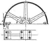
Fig. 24.
Another tensile stress is induced in the rim bolts by the fact, that, having made an open joint in the rim, and in addition placed the extra weight of lugs there, the centrifugal action at this point is increased, and at the same time a point of weakness in the rim introduced. Referring to Fig. 24, the rim flanges EJ tend to fly out due to the centrifugal force CF. This tends to open the joint J at the outside of the rim; to throw a bending stress on the rim, maximum at the point F; and to "heel" the rim flanges about the point E. The rim bolts acting on the leverage e about the point E must resist these tendencies, and are thereby put in tension.
Referring to equation 18, we find the intensity of stress due to the centrifugal force of the rim in lbs. per square inch to be :
P = v2 / 10
If A is the sectional area of the rim in square inches, this means that the total strength of the rim is represented by Av2 / 10 The strength of a bolt is represented by the expression Snd1 2 /4 . If, now, there are n bolts in the flange, the total resisting force of the bolts is nSπd12 / 4; and the equation represent, ing equality of strength between rim and bolts is :
Av2 / 10 = nSπd12 / 4, (28) from which, by a proper assumption of the fiber stress S, which should be low, the opening-up tendency of the joint being neglected, the diameter at the root of the thread dl may be calculated, and the nominal bolt diameter chosen. Reference to the table for strength of bolts, given in the chapter on Bolts, Studs, etc., will be found convenient.
Fig. 25.
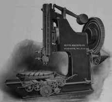
21-INCH SLOTTING MACHINE.
It is very doubtful if the tension on the flange bolts, due to the "heeling" about E can be calculated with sufficient accuracy to be of much value. It is probably better to assume S at a low value, say 4,000, and, in addition, for large and high-speed pulleys, stiffen the rim by running a rib between the flange and the adjacent arm. It is evident that if we make the rim so stiff that it cannot deflect, there will be no "heeling" about E; and the bolts will be well proportioned by the preceding calculation, giving them equal strength to that of the rim section.
For the bolt flange itself, any tendency to open at the joint J would cause it to act like a beam loaded at some point near its middle with the bolt load, and supported at J and E. This condition is shown in Fig. 25. Probably the weakest section would be along the line of the bolt centers. We have just noted that the carrying capacity of the bolts is nSπd12/4. Hence, assuming that e = ½ f, which is about the worst case which could happen, we have a beam of lengthy loaded at the middle with nSπd12/4 and supported at the ends. Equating the external moment to the internal moment, we have : nSπd12/4 x f /4 = s(L1 - nd)t22 / 6 (29) from which the fiber stress s in the flange may be calculated and judged for its allowable value.
L1 may be assumed a little narrower than the pulley face; and t2 from 1 inch to 2 inches or more, depending on the thickness of the rim.
The hub bolts doubtless assist the rim bolts in preventing the halves of the pulley from flying apart. They also clamp the hub tightly to the shaft, preventing any looseness on the key. Their function is a rather general one; and the specific stress which they receive is practically impossible to calculate. As a matter of fact, if the hub bolts were left out entirely, the pulley would still drive fairly well, but general rigidity and steadiness would be impaired. Hence the size of the hub bolts is more a practical question than one involving calculation. The rim bolts should be figured first, and their size determined on; then the hub bolts can be judged in proportion to the rim bolts, the diameter of shaft, the thickness and length of the hub, and the general form of the pulley. Often appearance is the deciding factor, it being manifestly inconsistent to associate small fastenings with large shafts or hubs, even though the load be actually small.
Practical Modification
Practical considerations are chiefly responsible for the location of the joint in a split pulley between the arms instead of directly at the end of an arm, where theoretically it would seem to be required. It is usually more convenient in the foundry and machine shop to have the joint between the arms; so we generally find it placed there, and strength provided to permit this. It is possible, however, to provide a double arm, or a single split arm, in which case the joint of the pulley comes at the arm, and the "heeling" action of the rim flanges is prevented.
The rim bolts should be crowded as close as possible to the rim in order to reduce the stress on them, and also the stress in the flange itself. The practical point must not be forgotten, however that the bolts must have sufficient clearance to be put into place beneath the rim.
While it is evident that the rim bolts are most effective in taking care of the centrifugal action of the halves, yet in small split pulleys it is quite common to omit the rim bolts and to use the hub bolts for the double purpose of clamping the shaft and holding the two halves together. The pulley is cast with its rim continuous throughout the full circle, and it is machined in this form. It is then cracked in two by a well-directed blow of a cold chisel, the casting being especially arranged for this along the division line by cores so set that but a narrow fin of metal holds the two parts together. This provides sufficient strength for casting and turning, but permits the cold chisel to break the connection easily.
Continue to:
My Books

