Anchor. Continued
Description
This section is from the book "The Engineer's And Mechanic's Encyclopaedia", by Luke Hebert. Also available from Amazon: Engineer's And Mechanic's Encyclopaedia.
Anchor. Continued
An anchor, differing materially in form and construction from the ordinary, was invented by Mr. R. F. Hawkins, and is represented in the subjoined engravings. The shank of the anchor a is forked at the lower part or crown, into two parts or loops b and c, in each of which is formed a hole or eve; between the loop.; is a block of iron d, termed a crown piece, having a circular aperture to receive the arms, and a square aperture at right angles to the former, into which is screwed a stout bar of iron e, termed a toggle, projecting equally on each side of the crown piece; on the end of the crown piece, opposite to that in which is inserted the toggle, is a ring f for the buoy rope. The arms g h are formed in one piece, and before the palms i i are attached, one end of the arms must be passed through the eyes in the loops of the shanks, and through the eye of the crown piece; the palms are then to be put on, and must both lie in the same plane; after which the arms are to be curved in the same plane with the palms.
The crown piece is firmly keyed to the arms, and the toggle must be of such a length and form as to make it bear firmly against the fore part of the fork in the shank, so as to prevent the crown piece and arms from turning round upon it, and to retain them at an angle of 50° with the shank. When the anchor is let go, one end of the toggle will come in contact with the ground, which puts the flukes in a position to enter; and when the strain is upon the cable, that end of the toggle which is upwards comes in contact with the throat of the shank, and sets the anchor in the holding position, as shown in perspective at Fig. 3. The advantage of this mode of constructing anchors is, that both arms take the ground, and therefore the weight of metal may be diminished, and yet an equal, if not a greater, effect he obtained; also as there is no stock, and no projecting upper fluke, there is little risk of fouling, as it is termed; that is, of the cable entwining round the arms. The only objection which occurs to us, is the probability that, when at single anchor, it might not so readily turn in the ground at the turn of the tide, as the ordinary anchor, and therefore might be likely to trip; but for moorings we have no doubt that it would be found very effective.

Fig. 1.

Fig. 2.
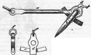
Fig. 3.

An anchor upon a similar principle, but of a somewhat different construction, was invented by Mr. Soames, a front and side elevation of which is exhibited in the subjoined cuts. In this anchor there is but one fluke a, which is T shaped, and works on a pivot in a triangular frame, composed of the two sides b and c, forged in one piece, and a stay d, which serves as a stock; f f are loops, or eyes, for the reception of the chains that unite the ring g, to which the cable is to be fastened. For general purposes, this anchor is, perhaps, preferable to the former, it being free from the objection we made to that one, as it admits of detaching the arm, which renders it more convenient to stow away; also, as the shank is formed in two parts, instead of one of equal area, they are more easily forged, soundly, and, consequently, less liable to breakage.
The anchor invented by Lieut W. Rogers, R. N. is deserving of notice in this place. Its main peculiarity consists in its having a hollow shank, formed out of six bars of iron, of such a thickness as to insure the forging of them perfectly sound for anchors of the largest dimensions. The construction we shall describe with reference to the subjoined figures. Fig. 1 represents a side view of the anchor, and Fig. 2 a plan of the stock. The two principal pieces a a are bent go as to form a part of the arms or flukes; the other four are formed into a hollow tube b b (as shown in section at Fig. 3) for a centre-piece, and the whole are firmly welded together at both ends of the shank. The intermediate parts are secured by strong hoops i i, so that every piece must bear its proportion of the entire strain. The patentee states, that so great is the strength thus obtained for the shank, that both arms have been broken off by the testing machine, without altering the shank in the least degree. On the 11th of June, 1829, an experiment was made at the Gateshead iron-works, in the presence of several respectable ship-owners, when the patent anchor, weighing 9 cwt. 19 qrs. 4 lbs. broke in succession the following anchors on the old construction, without receiving the least injury; viz. one of 10 cwt. 3 qrs. 4 lbs. for hempen cables; one of 10 cwt. 2 qrs. 12 lbs. and one of 12 cwt. 4 lbs. for chain cables.
In place of the usual ring, there is a bolt and shackle c, Figs. 1 and 4, when the anchor is to be used with chain cables; but when hempen cables are to be used, a ring d is connected to the shackle c by an additional shackle and bolt e. The anchor-stock f may be formed either of a single piece, or of two pieces hooped together, and is secured in its place as follows: The bolt and shackle c being withdrawn, the small end of the shank is passed through the eye of the stock f, (which is defended by an iron plate g on each side); the collar h is then put over, and the stock is keyed up against the hoop i by the forelock key k passing through a hole in the shank; by this means the anchor may be stocked or unstocked without the assistance of a carpenter, which is a great recommendation, as a considerable length of time is required to stock an anchor in the common way. These anchors have been pretty extensively adopted, and several parties who have made trial of them have given satisfactory certificates of their efficiency.
In connexion with improvements on anchors, it may not be altogether out of place to mention some improvements in the method of letting them go.

Fig. 3.

Fig. 4.

Fig. 1.

Fig. 2.

Two improved methods of letting go anchors are described in the Transactions of the Society of Arts. The principle is the same in each, and consists in supporting the end of what is termed the standing part of the cat-head stopper and shank-painter, by bolts turning upon pivots, and retained in a proper position by a catch, which being withdrawn, the bolt turns upon its pivot, and the stopper slips off, by which means all risk of jamming the turns of the stopper (as in the common method of letting go the running end) is avoided; the danger to the men on the forecastle is done away, and the anchor can be let go at a moment's warning.
The arrangements in each of these inventions being the same, whether applied to cat-head stoppers or shank-painters, we shall therefore show one invention as applied to cat-head stoppers, and the other to shank-painters. The subjoined cuts show Capt. Burton's method of letting go a cat-head stopper a is the cat-head; b c a bolt, turning upon a pivot d; the end c forms an oblique plane, and is held down by the clamp e turning upon a pivot f, the clamp being secured by a hasp g and pin h. i is the standing end of the stopper, having an eye formed in it, which passes over the end b of the bolt b c; the other end of the stopper passes through the ring of the anchor, and over the thumb-cleat k, and is made fast round the timber-head I. When it is required to let go the anchor, a hand-spike is inserted between the thumb-cleat k, so as to nip the clamp e, and the hasp g is cast off; then upon withdrawing the hand-spike, the bolt being no longer held by the clamp e, turns upon its pivot d, by the weight of the anchor on the stopper, and the eye of the stopper slips off the end of the bolt. The following cut represents Mr. Spence's invention for letting go a shank painter.
Fig. 1 is an elevation, and Fig. 2 the plan, a is a cast-iron carriage, bolted through the ship's side, and supporting the hook b by a pin or pivot at c; de a lever turning upon a centre , the end d being formed into a hook, which clasps the upper end of the bolt b, the lever being retained in the position shewn in the plan, by a pin g; h is part of a chain forming the standing part of the shank-painter, and supported by the bolt b.

To the other end of the chain is spliced the running part of the shank-painter, which passes round the shank of the anchor, and is made fast to a timber-head.
When it is required to let go the shank-painter, an iron bar is inserted into the end e of the lever d e, which is made hollow for the purpose, and the pin g being withdrawn, the lever is turned round its centre until the bolt is released from the hook d, when it falls, and the chain end of the shank-painter slips off.
Continue to:
My Books

