Gas Lighting. Part 7
Description
This section is from the book "The Engineer's And Mechanic's Encyclopaedia", by Luke Hebert. Also available from Amazon: Engineer's And Mechanic's Encyclopaedia.
Gas Lighting. Part 7
The next valve to be described is the one which is fixed at the bottom of each reservoir or lamp, for the purpose of filling them in the manner described in the preceding part of our subject; the annexed cut represents a section of one of those valves. This filling valve consists of a small conical plug g, which is fitted into a conical cavity or seat in the piece of metal c, similar to the valves of an air-gun, being closed by a slight steel spring h, and guided in its way by a metal pin, which slides through a hole in a small brass cap or perforated cover i, represented as screwed over it; d shows a brass plug, which is intended to be screwed into the lower aperture of the piece c, after the filling is completed. The upper surface of this screw-plug is furnished with a soft metal ring or collar, b b (as in the before-mentioned valve), which being pressed, by the force of the screw, into contact with the under side of the piece c, effectually prevents any escape of the gas from that end of the reservoir, even if the filling valve g should not be quite air-tight.
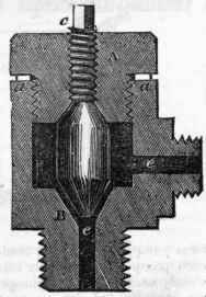
The following figure represents a section of the third and last of these valves, and its use is to permit the flow of gas to the burner to be regulated with great nicety and precision. The passages for the gas, e e, are drilled out of one solid piece of metal, and the regulating screw c is tapped into the side of the same piece; the lower part of it is adapted to screw into an aperture at one end of the reservoir of the lamp, when the regulating steel screw c is screwed up so that its conical end fits tightly into the conical cavity, - it closes it perfectly, and prevents all escape of gas to the burner a; but on turning the regulating screw slightly round by its square head, the gas escapes through the passages e e to the burner, in any degree that may be desired. Previously to inserting the regulating screw, it is dipped into a mixture of bees' wax and oil, which fills up every minute cavity or space which may be left between the threads of the two screws.
The engraving on page 602 represents a contrivance for delivering gas to the consumers in its natural volume, under atmospheric pressure. It consists of a collapsing gasholder, capable of containing upwards of 1000 cubic feet of gas; it is mounted on wheels; and being charged at the gas works, the gas is conveyed wherever required. The invention forms the subject of a patent to Messrs. Coles and Nicholson, and is, we believe, made use of by the Portable Gas Company at Manchester, in addition to the gas-condensing apparatus erected at their works at that place. Fig. 1 represents a plan of the cart, with the top of it removed; Fig. 2 is a side elevation, and Fig. 3 a front elevation; Fig. 4 is merely an enlarged section of the box marked d in Fig. 2. The recipient is composed of two distinct parts or halves, a and b; the upper part a is made of some flexible material, impervious to gas; and the lower part b of some comparatively stiff and inflexible substance; when the vessel is empty, the part a, turning itself inside out, falls down inside of b; the vessel is filled by forcing the gas from the works through a pipe, which is screwed into a nozle at f, provided with a stop-cock, which is turned off after the recipient is fully inflated, and the supply pipe from the works removed.
The machine then travels through the streets, and stopping at a customer's door, one end of a flexible pipe is screwed into the gasholder of the house, and the other end into a nozle in the box d, which communicates with the interior of the recipient by means of intermediate valves shown at Fig. 4. The gas-exhauster c is then put in motion by the handle at the top, and at every exhausting stroke is filled with
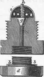

Fig. 1.

Fig. 2.

Fig.3.

Fig.4.

gas from the gas cart through the valve g, Fig. 4; and at each forcing stroke, the gas is discharged through the valve h, and along the flexible pipe into the gasholder of the house, until the required quantity is transferred. The gas cart thus proceeds from house to house, until the whole load is discharged. Along the bottom of the cart is a pipe e, connected at one end with the stop-cock f, and at the other with the box d of the exhauster, and perforated with numerous small holes, for the purpose of allowing the passage of the gas along the bottom of the cart when the flexible top lies over it. Since the foregoing account of the Portable Gas Machinery was prepared for the press, we have been informed that it has been nearly superseded by subsequent improvements in the manufacture and management of coal gas; nevertheless, the subject possesses sufficient intrinsic merit for our pages, as much of the mechanism is applicable to other purposes.
The " Domestic Gas Apparatus," shown in the following engraving, is an invention of Mr. Pinkus, for the manufacture of gas on so small a scale as to be adapted to private houses. An apparatus of the kind was exhibited in use Fig.2 for a considerable time in the Strand, and we believe the invention has been adopted in various extensive private establishments and small manufactories. Fig. 1 is a front elevation; Fig. 2 a lateral section of the apparatus; Fig. 3 a action of the retort; and Fig. 4 a section of a retort of a different constiuction; Fig. 5 is a section of the condenser. In each bottom figure the same letters refer to the same parts, a, Figs. 1 and 2, shows its application to a kitchen range, but it is equally adapted to any other common fire-place; b b, Fig. 2, is a recess or furnace built in brick at the back of the fire-place, covered in front by an iron plate c, and having a flue d opening into the chimney; e, Figs. 1, 2, and 3, is a cylindrical retort, divided by two or more internal partitions, radiating from a conical pipe f, as shown in Fig. 3.
Continue to:
My Books

