Melting's Patent Couplings And Breaks
Description
This section is from the book "The Engineer's And Mechanic's Encyclopaedia", by Luke Hebert. Also available from Amazon: Engineer's And Mechanic's Encyclopaedia.
Melting's Patent Couplings And Breaks
To obviate the inconvenience and waste of power by the slipping of the wheels of locomotives on railways, when they are in a wet or greasy state, Mr. John Melling, of Liverpool (the manager of the locomotive department of the Manchester and Liverpool railway,) has devoted much of his attention. In the specification of his patent granted in July, 1837, and reported in Newton's Journal for January, 1841, (whence we derive the following account,) he observes:-
"My improved method of coupling the engine wheels is effected by the application of a pair of friction wheels or rollers, of any suitable diameter, placed between the peripheries of the driving wheels, and the running wheels of the locomotive carriage. This assistance is, however, only required in those instances where the weight upon all the wheels is not uniform, or sufficient to prevent some of them slipping upon the rails; the quantity or degree of friction being readily accommodated to circumstances, and the connexion or coupling between any two wheels, whatever their respective diameters may be, produced or removed at pleasure. This contrivance is very advantageous in comparison with the ordinary previous mode of coupling, because, if the rails be dry or the adhesion be sufficient, the anti-friction wheel couplings may be lifted off and remain unused, while the ordinary system of outside cranks and connecting rods must always continue working, and thus, at certain times, only act as an incumbrance. Another important feature in this improved mode of coupling the wheels, is the smoothness with which the engine works when the cranks are passing their centres, instead of being subjected to the sudden blows and jerks which occur to engines coupled in the ordinary manner.
This improvement is effected by transmitting a considerable portion of the weight from the cranked or driving axle to the straight or independent axle, which entirely prevents the tremulous lateral motion of ordinary locomotive engines; passing over inequalities in the surface of the road; and tending greatly to prevent the destruction of the engine springs, and the beating of the rails, usually attendant upon such occurrences.
In the subjoined engravings Fig. 1 represents aside elevation of a locomotive engine, in which the before-mentioned improvements are introduced, and some others which we shall describe afterwards. To avoid confusion, many of the ordinary details of a locomotive engine are left out as unnecessary to our present object.
Fig. 1.
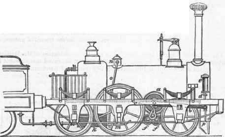
At a is the improved coupling wheel, in its proper position for connecting the driving wheels upon the crank shaft, with the running wheels upon the fore axle of the engine. One of these coupling wheels or rollers is placed on each side of the engine, and bearing upon the periphery of the driving and running wheels; they are suspended in wrought iron levers b, the fulcra of which are at the end c, and the other ends of these levers are attached to piston rods d, which work in small steam cylinders e e, which have a steam cock in common, to admit the steam from the boiler. Now it will be seen that when it is necessary to couple the engine wheels, in order to obtain more adhesion upon the rails and prevent the slipping of the engine, the cock is to be opened, which by letting steam into the tops of the cylinders causes their pistons to descend and depress the levers, which forces the coupling wheel a into contact with the peripheries of the driving and running wheels of the engine, as long as the steam is allowed to remain in the cylinder.
When the coupling wheel is no longer required to act upon the engine carriage wheels, it may be dispensed with, by turning the steam in at the bottom of the small cylinders, which raises the pistons and levers, and consequently lifts the coupling rollers from off the peripheries of the driving and running wheels. These coupling wheels are formed with a groove in their peripheries, wherein the flanges upon the tire of the carriage wheels run, and serves to keep them effectually in gear, and at the same time prevent the distance between the wheels ever becoming too narrow for the width of the rails, in the event of the wheels loosening upon their axles, which occurrence has frequently thrown the engine off the line of railway. Thus it will be seen, that the wheels of the engine may be coupled and uncoupled at any rate of speed they may be running, and without difficulty or interruption, without any restriction as to dimensions in the driving, running, or coupling wheels. (It is also deserving of remark that this coupling wheel is not confined in its application to locomotive engines, but may be applied as a medium for driving all kinds of machinery, in order to dispense with any jerking or uneven-ness of motion occasioned by toothed gearing, or in order to obviate the difficulty frequently arising from the teeth of wheels breaking).
In connexion with the before-mentioned apparatus and illustrated by the same figure is an improved drag or break. At ffare two small anti-friction rollers, suspended from the levers b, their own peripheries being in contact, but hanging in guides h h, entirely free from the peripheries of the engine carriage wheels; and when it is necessary to stop the engine, it may be done with great rapidity and ease by letting the steam into the bottom of the cylinder e, thus raising the lever b (at the same time releasing the coupling wheel a), and bringing the peripheries of the two rollersff into close contact with the tires of the engine carriage wheels, and thus effectually to lock them or impede their progress, by immediately reversing the direction of the revolution.
The same system of apparatus is applied to the tender, but with a different mode of putting the same into operation, as the rollers are there drawn into contact by a vertical screwed rod and suspended links; which construction will be found most suitable for tenders and carriages used for the transit of passengers and merchandize.
The annexed diagram is explanatory of another modification of Mr. Melling's friction couplings, which he considers to be also an improved arrangement for such engines as are employed to convey heavy trains and merchandize.
Fig. 2.
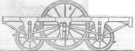
At a is the main cranked or driving axle, in the centre of the engine; upon the ends of this axis, two large driving wheels b are fixed, so as to run just clear of the rails; but so as to bear forcibly upon the fore and hind wheels c c, and thus transmit the power of the engine through them, and obtain a perfect adhesion upon the rails at all points.
With a view of showing in a strong light the great practical advantages attending the patent coupling wheels, Mr. Melling exhibits two diagrams in his specificatioii representing the wear upon the tire of a wheel by the use of his coupling, and without if, which we shall herewith add.


Fig. 3 represents the amount of wear upon the true cone of the tire of wheels of engines that have run without being coupled, and therefore entirely the effect of slipping against the rails. Fig. 4 shows a wheel which has performed the same number of journeys as the other, but which has been coupled according to the patentee's method. In the latter, owing to the entire prevention of slipping, there is no perceptible wear.
Another improvement effected by Mr. Melling, and described in the London Journal for January 1841, consists in a combination of apparatus for working the slide-valves of locomotive steam engines, which he states "entirely dispenses with.the imperfect mode of working them by excentrics," as hitherto practised. The great reduction of friction effected by it is equivalent to a corresponding increase of power. "A farther improvement, arising from this mode of working the slide-valves, is, that they are driven from the ordinary connecting rod instead of being worked by excentrics mounted on the crank shaft, as heretofore; in which case, if by any accident the crank shaft happened to have become bent or broken, it could not effect the opening and closing of the side valves. Having now given several external views of the more modern form of six-wheeled locomotive engines, and their principal accessories, we shall proceed to exhibit the internal construction of the parts, by an enlarged section of an engine constructed by Messrs. Tayleure and Company,and shown on the following page.
At a a a is the boiler, consisting of a horizontal cylindrical chamber connected to a vertical chamber, containing within it the fire box b, which is surrounded by water, ccc are a series of horizontal tubes of small diameter, serving as flues through which the heat is imparted to the horizontal portion of the boiler, and opening into the smoke box d, which is surmounted by the funnel or chimney e, shown as broken off for want of space. Atf is a bell-mouthed pipe (rising up within a dome to prevent the water passing over with the steam), which communicates with the throttle valve g, whence the steam is conducted by branch pipes h to the two cylinders i. Atj is the slide valve, k the eduction aperture communicating with the blast pipe l: m is the piston rod, n the connecting rod o one of the driving cranks formed upon the axle, p one of the excentrics which govern the motion of the slide-valves.
At q is one of the driving wheels, r the feed pipe, the supply of water being regulated by the cock * through the medium of the key t; v is the connecting link, to the hand or starting gear, x x the steel-yard safety valve, y the man hole, and z the buffer.
It may be observed that the boiler is encased with wood to prevent the loss of heat from radiation; and for the same purpose the steam chests, or domes and man holes, are provided with a thin metallic casing (generally of brass) leaving a narrow space of air between them. The top of the chimney is covered by a cage of coarse wire-work to prevent the escape of red-hot cinders, for the want of which precaution many accidents have occurred.
Continue to:
My Books

